This article is to understand the process control and instrumentation system in our chemical process industries. Which is very important for stable and efficient operation of any plant.
In a chemical plant to achieve desired output with desired quality and capacity we need to control the process parameters. For each process parameter we have an operating range namely low value and high value. Apart from this we have one set point value also. Therefore, process control system continuously works to maintain the actual value of process parameter as much as close to the set point value. Moreover, in most of the plants, control of process parameters is very critical from safety and environment point of view.
Table of Contents
Process Parameters in a Plant
We can divide various process parameters in a plant in four categories as below:
- Input Process Parameters – These can be such as raw material feed flow rates, input stream & utilities feed flow rates, their temperature and pressure. Moreover, other input process parameters like feed composition & impurity level are also there. However, these are beyond the control limits of process control system generally.
- Output Process Parameters – This comprises parameters like product and effluent flow rates and their pressure, temperature, compositions & other quality parameters.
- Within Process Parameters – This means those parameters which are required to maintain within a process equipment. It is like distillation column temperatures and pressures or reactor temperature and pressure.
- External Parameters – The fourth category includes parameters which are outside the process control limits. These are for example, ambient temperature, wind velocity, rain, sunlight, etc.
Components of a Control System
To design a control system for a process we need to develop a mathematical model first. This model enable us to understand the relationship between the process parameters. In below figure you can see different parts of a typical process control system. For the help to develop mathematical model for batch reactor please follow below link:
Mathematical Model for Batch Reactor
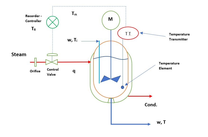
Process (Agitated Batch Reactor)
In a process inputs convert into outputs by series of logical, chemical and physical change steps.
Measuring Element
(RTD or Thermocouple), for other control systems it can be orifice meter, pressure transmitter, level transmitter. Every measuring element comprises two parts, first measuring element and second transducer. Elements measure the controlled variable and transducer converts this variable into electrical signal in the range of 4 – 20 mA. This signal further enters into the controller.
Recorder & Controller
Controller takes 4 -20 mA electrical signal from the transducer. And, converts the error (ϵ = TM – TR) to an output in the range of 4 – 20 mA.
Final Control Element (Control Valve)
Control valve has a valve positioner mounted on it. This valve positioner works as converter, it converts electric signals from controller to pressure range of 3 – 15 psig. This output is linear or equal percentage function of the input signal. Finally, this pressure adjusts the valve opening through diaphragm, which controls the flow of steam to minimize the error in controlled variable.
You can see above all components in any control system physically, such as RTD, orifice, transmitters, control valve, controller, etc. In other words, these four components will constitute most of the control systems. In above diagram you can see three signals TR, TE and Ti.
- TR is the Set Point value or a desired value of the process parameter. Here, process parameter is reactor temperature (T) which is a controlled variable.
- Ti is the load variable, any change in this variable will disturb the reactor temperature. In other words, we can say if there is any change in input stream temperature, it will change the process temperature also. Other load variables for this process are input feed flow rate disturbance, steam flow rate disturbance, steam temperature disturbance and steam pressure disturbance.
- TM is the measured value of the inside process parameter. In other words, this is the actual reactor temperature at that point of time.
Pneumatic and Electronic Controller Hardware
You can see tremendous developments happened, during the course of transformation in process control hardware. In 1940s pneumatic controllers were used predominantly. In this type input and output signals to and from and within controller were air pressure signals. These air pressure signals usually varied in the range from 3 to 15 psig. Various components of this controller are as below.
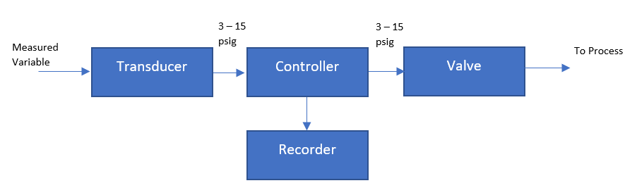
Subsequently, due course of development electronic controller and analog computer came into picture. This electronic controller mimicked the control functions of the pneumatic controller. These were improved controllers and provided the facility such as accurate and reproducible control parameter settings. Moreover, these controllers were smaller in size. Below figure shows components of an electronic controller.

Microprocessor-Based Controller
In the 1970s first generation digital control hardware came into market. This was based on advanced microprocessor-based technology. This system was user friendly and easy to use for plant operators. Controller configuration was also very easy in this. The components of microprocessor-based controller can be seen in below figure.
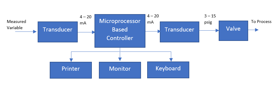
A microprocessor-based controller works based on an algorithm. And, various features of this type of control system are below:
- Implement the control algorithms
- Provide display on the monitor (includes static & dynamic)
- Gives alarms for process variables
- Mathematical functions can be deployed
- We can store and retrieve data for process parameters
Microprocessor-based controller performs all above tasks with help of supporting software. And control system manufacturer supplies these software with the hardware.
Industrial Control Systems (ICS)
ICS is a common name of various control systems and associated instruments. This include the devices, systems, networks, and controls used to operate and/or automate industrial processes. In our industries there are many types of ICSs, but bellow is some common one.
Distributed Control System (DCS)
Standalone controllers do not communicate with each other. They have dedicated controller for every controlled variable. While, DCS or distributed control system is a microcomputer-based control system, in this controller can communicate with each other through a network. In a DCS we can have any number of control loops. DCS is good for use in large manufacturing facilities like refineries, power plants, continuous chemical plants, etc.
Supervisory Control and Data Acquisition (SCADA) systems
SCADA is not a system that can provide full control. Instead its capabilities are focused on providing control at the supervisory level. SCADA systems are composed of devices (generally Programmable Logic Controllers (PLC) or other commercial hardware modules that are distributed in various locations. The primary purpose of using SCADA is for long distance monitoring and control of field sites through a centralized control system. We can see SCADA installations in industries such as, involving pipeline monitoring and control, water treatment centers and distribution, and electrical power transmission and distribution.
Programmable Logic Controller (PLC)
Both DCS and SCADA systems uses PLCs as a control component of an overall system. It also provides local management of processes being run through feedback control devices such as sensors and actuators. In DCS, PLCs are used as local controllers within a supervisory control scheme.
Control Strategies for Advance Control
In our plants we have all control loops are single loop controls. In other words, single loop has one controller and one measuring element. Many times, you need a precise and effective control of the controlled variables. Therefore, to achieve this objective we can follow below strategies. These solutions are superior than a single loop control method.
Cascade Control
Other name of cascade control is master and slave control also. In this there are two control loops master control loop or primary control loop and slave or secondary control loop. Primary control loop provides setpoint to the secondary control loop. Secondary control loop works based on this setpoint. This way variation reduces in primary controlled variable. The Example for this can be controlling the reactor temperature from jacket temperature control. Here, reactor temperature controller gives setpoint to jacket temperature controller. Since jacket temperature is responsible to maintain the reactor inside temperature.
Feedforward Control
These type of control strategies are predictive controls in nature. Here, disturbance is predicted before entering into the system and controller takes required action in advance. This prediction of controlled variable you can get from the knowledge of process modelling. And, the case where model is not available, you can generate data for controlled variable using open loop step changes. Moreover, where load disturbance measurement or anticipation is not easy, we use the combination of feedforward & feedback control system.
Ratio Control
This is very common in our industries. We can see the examples of feed streams (i.e., say A, B & C) in a continuous reactor. Here we feed ‘B’ & ‘C’ feed streams in the ratio of ‘A’ feed stream. The flow measurement of feed stream ‘A’ compute the set point for the other two feed streams.
Multivariable Control System
We see in plants there are multiple-input multiple-output systems (MIMO). However, installed control systems are fundamentally single-input single-output (SISO). If there is disturbance in a variable it will impact other variables also. And, installed respective single loop control systems try to control their respective variables. In other words, there is no communication between these variables and variation can propagate beyond the controlling limits. In that case, DCS operator takes the process controls in manual mode. Then, DCS operator follows the standard operating procedure and in process skills to restore the process at steady state.
Therefore, we can see DCS operation is dependent on the DCS operator skills & efficiency. So, to eliminate this dependency, multivariable control system is the solution. A multivariable control system can take multiple inputs and based on the process models & algorithms can generates multiple outputs to the controllers. This way MIMO control system can generate efficient & effective control for our process.
Advance process control or APC is a multivariable control. This APC works above the distributed control system. These systems are intelligent and efficient than basic process control system.
Conclusion
In this article focus was to understand the control system only, while other part is instrumentation. Which includes field instruments such as pressure gauge, temperature gauge, level gauge, rotameter etc. Other than there are panel instruments like temperature indicators, level indicators, pressure indicators, flow indicators, etc. These all are visible on DCS computer screen.
Now industries are moving towards digital transformation, where you can record and analyze real-time data. This will help us to make effective & efficient decisions for process operation. Moreover, machine learning will empower to derive artificial intelligence in plant operation. Which will elevate plant operation to the next level, where plant processes will be predictive and self-diagnostic in nature. For more information about chemical plant digital transformation, you can read my article Need of Digitalization in Chemical Plant.
Thanks for reading and looking forward for your feedback and comments.