In chemical process industries we use control valves to regulate the flow of fluids. This fluid can be liquid, gas or sometimes liquid slurry. We need control valves to control various parameters such as level, pressure, temperature, flow, feed ratio, etc. These control valves can be pneumatic or electric operated. In our industries, we use pneumatic control valves primarily. And, in this article we will discuss about the control valve process data sheet.
So, to get the insight about control valve PDS, let us go through the below format.
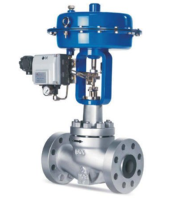
Table of Contents
Format of Vessel Process Data Sheet
This is a typical process data sheet format for a control valve. It contains following main sections.
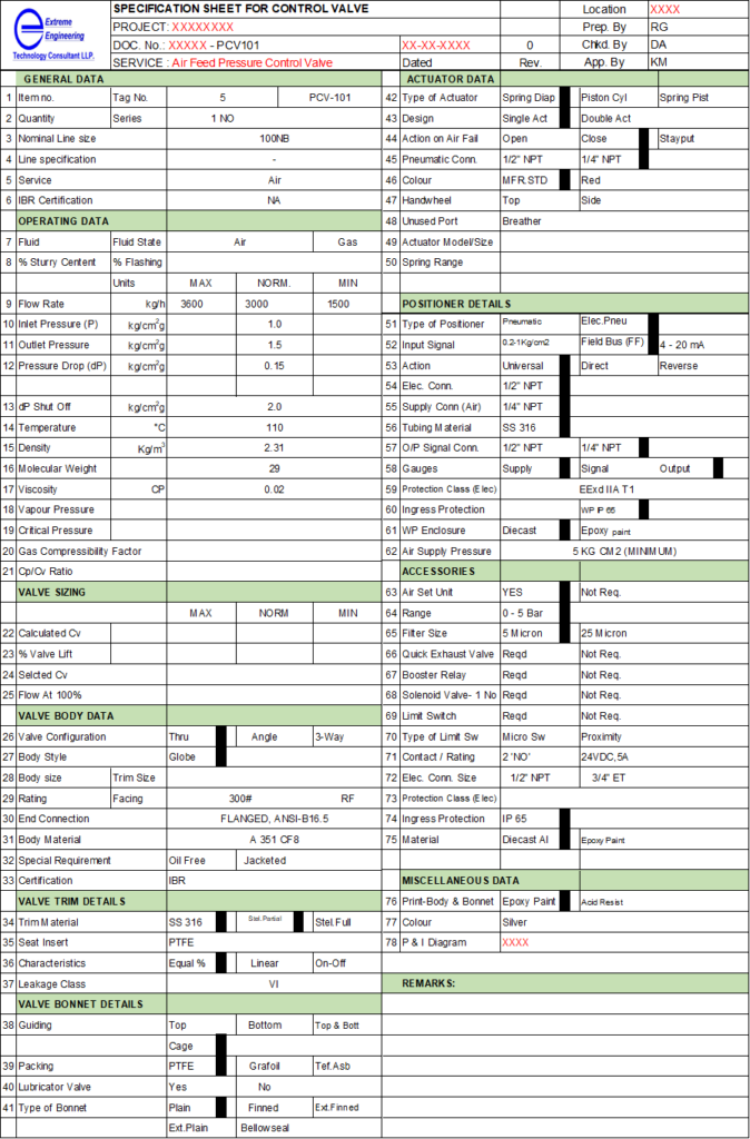
Top Header
This includes the identification of the process data sheet or specification sheet. You should put the logo and name of your organization. Information such as control valve description, document number and project name are very important during erection work. As, this helps the people at site for easy and errorfree identification of that particular control valve.
Other details include are plant location, revision number which are important from documentation point of view. Apart from this, details of maker, checker and approver are important to trace the engineers involved in this project.
General and Operating Data
In general section, data comprise Tag. No., quantity, line size, service fluid details, pipe line specification. Apart from these, whether this valve require IBR certification or not, however it is applicable for steam service above 2.0 kg/cm2g pressure.
In operating data, you need to mention operating data and fluid properties for the control valve. This information includes like, fluid details (i.e., composition), flow rate, fluid density, viscosity, operating pressure & temperature. Apart from this we need to mention gas compressibility factor and Cp/Cv ratio in case of compressible fluid.
Valve Sizing Data
In process data sheet, this information either process engineer can estimate or supplier can provide based on the operating data as given above. In order to specify the size of a valve in terms of its capacity to provide flow at 100% opening, we can use below equation:
q = Cv * (∆Pv/G)0.5
Where, q = flow rate, gpm
∆Pv = pressure drop across the wide-open (100%) valve, psi
G = specific gravity of the fluid at operating temperature relative to water
Cv = factor associated with valve capacity
Valve suppliers rate the valves in terms of factor Cv. As the valve Cv increases its size also increases. As a rule of thumb for a sliding stem and plug type control valve, you can estimate Cv as below:
Cv = (Valve Size)2 * 10
So, for 3.0-inch control valve, Cv = 3*3*10 = 90
Valve Body/ Trim/ Bonnet Data
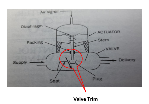
In these three sections of data sheet, we provide various important details related to the control valve construction. To understand the control valve internals, you can refer below sketch:
In body section we can provide valve type (i.e., globe, gate, ball, butterfly), valve body and trim size, flange rating, end connection and piping standard, body material, any special requirement (i.e., jacketed), etc.
Valve trim details includes stem, valve plug and seat ring as you can see in above figure. So, you can mention required material for seat, plug and stem. Trim stellite requirement (i.e., partial or full) and characteristic of trim like equal %, linear or on/off. Stelliting provides good relative hardness and corrosion resistance to the trim, which is heart of a valve. Various stelliting materials for corrosion resistance are special alloys, such as Alloy-20, Hastelloy-C and Monel.
Valve bonnet details we can provide like its guiding type, packing material between stem & valve body, type of bonnet (i.e., plain, finned, bellow seal, etc.)
Actuator & Positioner Data
For pneumatic actuator pressure to the valve varies from 3 to 15 psig for the motion of valve stem from a fraction of an inch to several inches. This range of actuators is provided by the control valve vendors and varies according to valve size. Valve actuator action incase of air fails is very important, you need to specify this based on your process requirement. It can be either air fail to close or fail to open type. Fundamentally, all steam flow control valves should be fails to close type and pressure control valves fails to open type. Other various information for the actuator is mentioned in above data sheet, which you should provide.
In control valve, positioner is a motion-control device designed to actively compare stem position against the control signal. It adjusts pressure to the actuator diaphragm or piston until the correct stem position is reached. Here we need to provide the details like type of the positioner, input signal type (i.e., HART or Foundation Field Bus), action type (universal, direct or reverse), various connection types of for air & electrical, gage of air pressure, protection class from electrical and environmental exposure, material of construction, etc.
Remarks
In this section we can provide miscellaneous information, which are common. Based on your specific requirements this information can be customized. Whole purpose here is to provide all the general clarification to the vendor and user.
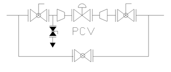
Control Valve Installation Consideration
Below are the important best practices which you should keep in mind during control valve installation:
- Don’t hold the control valve by tubing any damage or leakage from joints will impact the valve operation.
- Always install isolation ball valves with bleed valves in control loop. Pipe line should be at least one size larger than the control valve size.
- Avoid to install the control valve sideways and ensure always vertical installation in horizontal pipe line as you see in below figure.
- For process safety point of view, double check the air fail position for the control valve.
- Check the instrument air pressure and quality, should be clean and dry for efficient operation of the control valve.
Below is the typical piping arrangement for a control valve for your reference:
Conclusion
This article will help the process engineers, who are looking for the control valve data sheet preparation. Using above guidelines, they will be able to deliver their documents timely and correctly. Control valve is the part of a control loop assembly which includes a meter and sensor also. These meters & sensors we use to measure flow, pressure, level, temperature, etc. Various types of meters are like, orifice meters, RTD, TC, pressure transmitters, mass flowmeter, etc.
Thanks for reading.