Orifice type flowmeters are widely used in our chemical process industries. The reason behind this, is their low cost, easy installation and maintenance. Fundamentally, an orifice meter provides volumetric flow rates of the fluid and by multiplying it with fluid density we can get mass flow rates. Orifice type flowmeters gives very accurate flow rates measurement for incompressible fluids or liquids. While, in case of compressible fluids, density change is significant, error in flow measurement can be higher side. However, we can solve this problem by providing operating temperature & pressure correction factor to the fluid density. We need to measure fluid flow rates, so that we can measure it and control the flow rate to avoid variation in process. Also, the flow meter is an integral part of a flow control loop, which includes flow control valve. So, in this article we will discuss about orifice meter process data sheet.
First let us understand working principle behind the orifice meter.
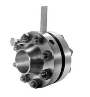
Table of Contents
What is an Orifice Flowmeter?
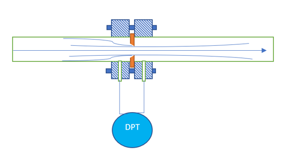
An orifice flowmeter is a head flowmeter type, in which we measure pressure drop across the known diameter orifice plate. This orifice plate is fixed in the pipeline with help of flanges. The thickness of these flanges is around 40mm and has threaded drilled holes for fixing the differential pressure transmitter like DPT or differential pressure transmitter. Using this DPT we measure pressure drop across the orifice plate. The volumetric flow rate through orifice is the function of pipe diameter, orifice plate bore diameter and pressure drop across orifice plate. You can refer below figure to understand the typical installation of an orifice flowmeter. Also, for better accuracy please ensure 10D and 5D straight pipe distances at the upstream and downstream of the orifice. Here D is the pipe diameter.
We use orifice equation to estimate the fluid flow rate through a pipeline, in this equation only variable is the DPT rest pipe diameter and orifice bore diameter are constants for a given orifice meter.
Orifice Equation
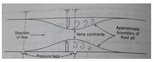
As you can see in below schematic, when fluid passes through a circular bore of an orifice it starts begin to converge at some distance from the orifice. It keep continue to converge to a minimum diameter as shown below as cross section at “2”. After this point it again starts to diverge up to the full diameter of the pipe. This section at “2” we know as the vena contracta and it’s diameter we can assume equal to the orifice bore diameter. We provide pressure tapings at section “1” and “2” to install a differential pressure measurement device.
Applying Bernoulli’s theorem for steady flow between section “1” and “2”, we can find the below equation to calculate the average linear velocity through the orifice.
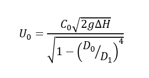
Above is known as Orifice Equation and various terms used are as below:
U0 = Average linear through orifice bore (m/s)
∆H = Pressure drop across orifice (meters)
g = gravity acceleration (9.81 m2/s)
D0 = Orifice bore diameter (meters)
D1 = Pipe diameter (meters)
C0 = Coefficient of discharge (it is 0.61 if Re through orifice >= 30,000)
After estimating velocity through orifice, we have orifice diameter & fluid density with us. So, we can estimate the mass flow rate through the pipe using below equation:
m (kg/s) = U0 (m/s) * pi*D02 * ρ / 4
Format of Orifice Meter Process Data Sheet
Below is a typical process data sheet format for an orifice meter. It contains following main sections.
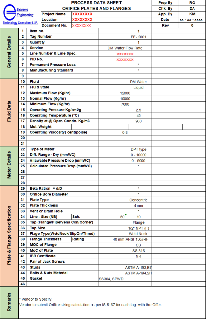
Top Header
This includes the identification of the process data sheet or specification sheet. You should put the logo and name of your organization. Information such as document number and project name are very important during erection work. As, this helps the people at site for easy and error-free identification of that particular orifice meter. Other details include are plant location, revision number which are important from documentation point of view. Apart from this, details of maker, checker and approver are important to trace the engineers involved in this project.
General Details & Fluid Data
In general section, data comprise Tag. No., quantity, line number, P&ID Number, Permanent pressure loss & manufacturing standard. About permanent pressure loss we will discuss in subsequent section.
The fluid data section contains, fluid name & composition, physical state of the fluid (i.e., liquid or gas), fluid flow rate both minimum, normal & maximum. Apart from these, operating & design pressure/temperature for the orifice meter, physical properties of the fluid such as density, viscosity, etc.
Meter Data
Here we provide the details related to meter, which will measure the pressure drop across the orifice. What is the type of meter like, local gauge, DPT (differential pressure transmitter), manometer, etc. We should mention range of DP measurement for the meter. Provide allowable pressure drop across the orifice (i.e., as a thumb rule it should be around 10% of upstream pressure) and calculated pressure drop is given by the orifice supplier. Or we can also design our orifice and provide the required bore size.
Plate & Flange Details
In this we provide all the information concerned with plate & flange assembly manufacturing. Such as MOC for plate & flanges, gasket type & it’s material of construction. Mention type of flanges (SORF, WNRF, etc.), flange thickness & rating, manufacturing standards.
Remarks
In this section we can provide miscellaneous information, which are common. Based on your specific requirements this information can be customized. Whole purpose here is to provide all the general clarification to the vendor and user.
Various Design Considerations in Orifice Meter
From above orifice equation we can see that, as pressure drop increases across orifice plate the bore diameter will reduce for given fluid flow rate. Because of this change in orifice bore diameter the value of [1 – (D0/D1)4]1/2 also changes, this term we know as beta (β). As this beta (β) increases, overall pressure loss decreases across the orifice. This is true for the case when we increase the fluid flow in a given orifice meter. The pressure recovery in orifice meter is poor, because of eddies formation. So, to achieve better accuracy (β) value should be between 0.20 and 0.75.
Also, you should keep on checking orifice bore diameters on half yearly or annual basis in your manufacturing plants. This is more important in the case of erosive & corrosive chemical service, where orifice plate bore diameter may enlarge with time. This will give wrong flow readings to the plant operator. Apart from this, we need to take care for pressure tapping location also, incase of liquid flow tapping should be either bottom side or 180 degree apart on horizontally. For the gas & vapour services we should provide pressure tapings on vertically top side on the orifice flanges. Therefore, during fixing or welding the orifice meter we must keep above things our mind. For any case if pressure measurement is not correct your orifice meter cannot give you actual flow rates.
Conclusion
This article will help the process engineers, who are looking for the orifice flowmeter data sheet preparation. Using above guidelines, they will be able to deliver their documents timely and correctly. Moreover, they can design orifice meter and install for the required service. Furthermore, process engineers can check and recalibrate the installed orifice meters inside the plants and revise respective DPT pressure settings accordingly.
Thanks for reading.