In chemical process industries distillation columns are widely used unit operation. And, based on the production capacities this can be batch distillation or continuous distillation process.
Table of Contents
What is Distillation Column?
Distillation column separate a feed stream having multiple components into two different streams based on the difference in boiling points. So, higher the boiling point difference easier the separation. While, for close boiling point components mixture separation is very difficult. Therefore, in case of close boiling mixture distillation we need very large height columns and high reflux ratio. Furthermore, when boiling point difference is around 1.5 degC or less we use azeotropic or extractive distillation method to separate the mixture.
The stream coming out from top and bottom of distillation column is distillate and bottom products respectively. In distillation column we supply heat from bottom via reboiler. And, use condenser to remove heat at the top. The component having low vapor pressure comes out from top, while high boiling point components comes out from bottom of the column.
So, to check the performance of a distillation column you need to do material and energy balance. This theoretical estimation tells you about gaps from the operating conditions. Afterwards, these gaps provides opportunities for improvements in terms of steam & power norm reduction. Further to meet this requirement there are various improvement techniques like column heat integration, pinch technology, heat pump in distillation, etc. Hence, we will consider an example to understand the material and energy balance around a distillation column.
In a typical continuous distillation column there are five control loops, column feed control, reboiler steam flow control, column bottom level control, reflux flow control and reflux pot level control. There there are five control valves in these control loops.
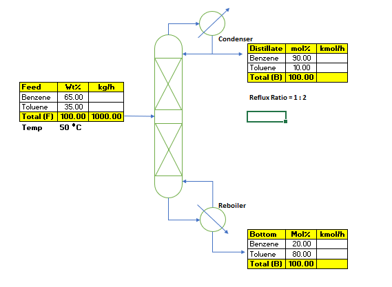
Operating Conditions Distillation Column
So, for our case we will consider a case to distill out the feed mixture containing benzene and toluene. The feed rate is 1000 kg/h of a mixture containing 65 wt% benzene and 35 wt% toluene. Top product purity is 90 mol% benzene and 80 mol% toluene in bottom product. Feed temperature is 50 0C and Reflux ratio for the column is 1: 2. In our example we are considering reflux at saturation temperature. However, in actual it is at sub-cooled reflux temperature and this affect the distillation column capacity and specific energy requirements. Column is operating at atmospheric pressure.
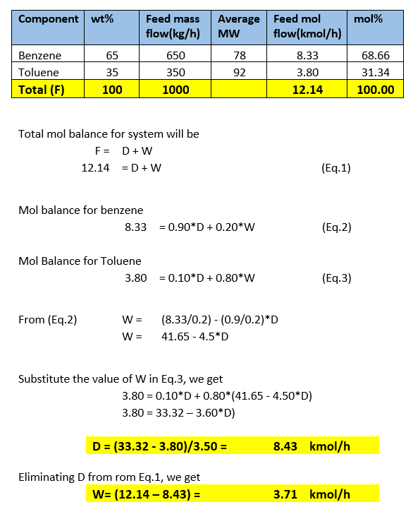
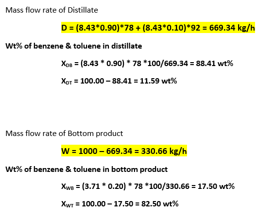
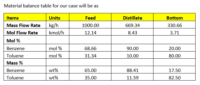
Material Balance for Distillation Column
We can convert feed composition in mole%
Heat Balance for Distillation Column
Feed temperature, Tf = 50 0C
Heat Capacity of Feed, Cpf = 0.42 kcal/kg-0C
Heat Capacity of Distillate, Cpd = 0.44 kcal/kg-0C
Column top temperature, Tt = 82 0C
Column bottom temperature, Tb = 104 0C
Latent heat of top product, HD = 94 kcal/kg
Latent heat of bottom product, Hw = 88 kcal/kg
Reflux ratio, R = 1 : 2
Vapor rates from column will be, V = D + 2 * D = 3 * 669.34 = 2008.02 kg/h
Heat load on reboiler will be,
Qb = F * Cpf * (Tb – Tf) + V * HD
Reboiler duty Qb = 1000*0.42*(104 – 50) + 2008.02*94
Calculated reboiler duty Qb = 211,434 kcal/h
So, heat load on condenser will be (assuming distillate is at 5 degC subcooled)
Condenser duty Qc = V * Cpd * (Tt – 5) + V * HD
Putting the numbers, Qc = 2008.02*0.44*(82 – 5) + 2008.02*94
Calculated condenser duty Qc = 256,786 kcal/h
Utility Requirement for Distillation Column
We are considering saturated steam @ 3.0 kg/cm2g is fed to reboiler for distillation column heat supply. The latent heat of steam is 507 kcal/kg. Assuming reboiler condensate is at saturated temperature. So, steam flow rate will be as below
ms = Qb/507 = 211,434/507 = 417 kg/h
For cooling water requirement, assuming cooling water supply temperature to condenser 32 degC and return temperature is 38 degC. Therefore, cooling water requirement for the condenser will be as follows
mc = Qc / (Cpw * (38 – 32)) = 256,786/(1*(38 – 32)) = 42,798 kg/h
Conclusion
However, you can do these calculations using process simulators like ChemCad, Aspen, Pro2 etc. In my view, during starting phase of your carrier always do process calculations by hand. This will enable you to visualize the process steps and moreover reinforce your confidence also.
Process simulators are like a black box, in this you give input variables and define few system parameters. And, after doing some iteration simulator generate an output. So, to interpret this output you need to understand how this calculation is done by the simulator. In this case if you have performed calculation by hand, then it will be very easy for you to check the simulator output.
Thank you very much for your reading looking forward for your comments.