We can find batch distillation column in almost every chemical process industry. Specially, you can find it more in fine chemicals, specialty chemicals, pharmaceutical and small-scale chemicals production industries. This is so because, batch distillation column requires lower fixed cost and provide higher operational flexibilities. However, batch distillation columns consume more energy than a continuous distillation column for the same service.
Major advantage of a batch distillation column over continuous distillation column is its operational flexibilities. In other words, by using single column we can distill different mixtures. Moreover, we can distill different quality & purity products from a single column only. Which is not possible in a continuous distillation column, where we operate at a fixed feed condition and for fixed product quality. As well as, in a continuous distillation column to separate N-components mixture in it’s purest form you require N + 1 distillation columns in series.
Table of Contents
Various Parts of a Batch Distillation Column System
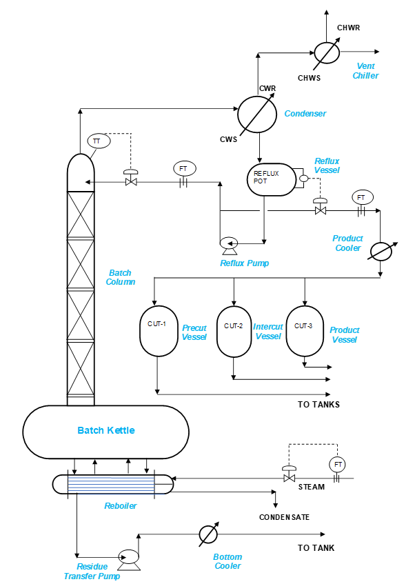
To understand a batch distillation column system, you can refer to below figure. The main parts includes batch kettle, batch column, batch column reboiler, batch column condenser, reflux vessel, product cut and intercut collection vessels and reflux pumps.
Batch Kettle
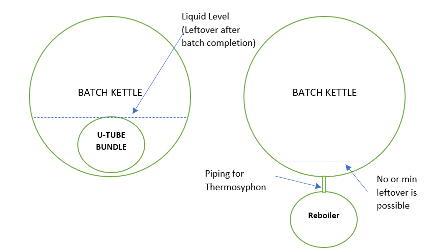
We charge the crude product mix or a solvent mixture in this, which we wish to separate. This is a cylindrical horizontal vessel having dished ends, sometimes it is vertical also. Material of construction and thickness of this vessel depends on chemicals we are handling and the operating conditions, such as pressure and temperature. To ensure safe operation we should provide a safety valve on this vessel. Moreover, proper insulation is important to eliminate heat loss from the large surface area of the kettle. At bottom, there are nozzles for hot liquid inlet and cold liquid outlet, which are connected with the reboiler. In many installations we can see for kettle heating u-tube bundle is installed inside the kettle itself. However, for minimum liquid leftover and uniform heating external reboiler is a better option. This we can understand from below figure.
Batch Column
Vapor from batch kettle goes into the column, this column is mounted directly on the kettle itself. You can also find the separate installation for the column, where column and batch kettle are connected with piping for liquid and vapor traffic. Inside column there can be trays, structured packing, random packing or combination of these (i.e., trays + packing). Mechanical design of column can be either in single piece or segmented. Segmented design of column requires plant structure or support structure for the access of column body flange bolts tightening. Columns having large diameters and for high pressure operating condition should be designed in a single piece. This will avoid the column leakage possibilities in the absence of the body flanges. Moreover, lower column fixed cost, as cost of large diameter body flanges & gaskets is too high.
Batch Column Reboiler
As we discussed earlier also that, for heating of batch kettle we can have u-tube bundle installed inside the kettle or provision of external reboiler. In case of internal u-tube bundle left over at the end of the batch is higher comparatively. Moreover, heating area also reduces when liquid level comes down below the u-tube bundle height. In this case because bundle is not submerged in the liquid pool, therefore overheating of upper side tubes faces frequent fouling/scaling problems.
In contrast with external reboiler we don’t face such type of issues. Reboiler tubes always remain submerged in liquid. And, provides almost constant heat supply to kettle mass throughout the batch . However, fixed cost is higher for this option, as cost of reboiler is higher than a U-Tube bundle.
Batch column reboiler can be of two type, first forced circulation and second natural thermosyphon. Wherever distillation kettle liquid is very viscous and very fouling in nature, it is better to go with forced circulation reboiler. As this will provide higher operating hours before the cleaning requirements. This is because high tube velocity will avoid scaling on tubes and will support high heat transfer coefficient in comparison with natural thermosyphon reboilers.
Batch Column Condenser
We can install condenser directly on top of the column or outside of the column for condensation of vapor. This is a shell and tube type heat exchanger. As you can see in below schematic diagram for reference.
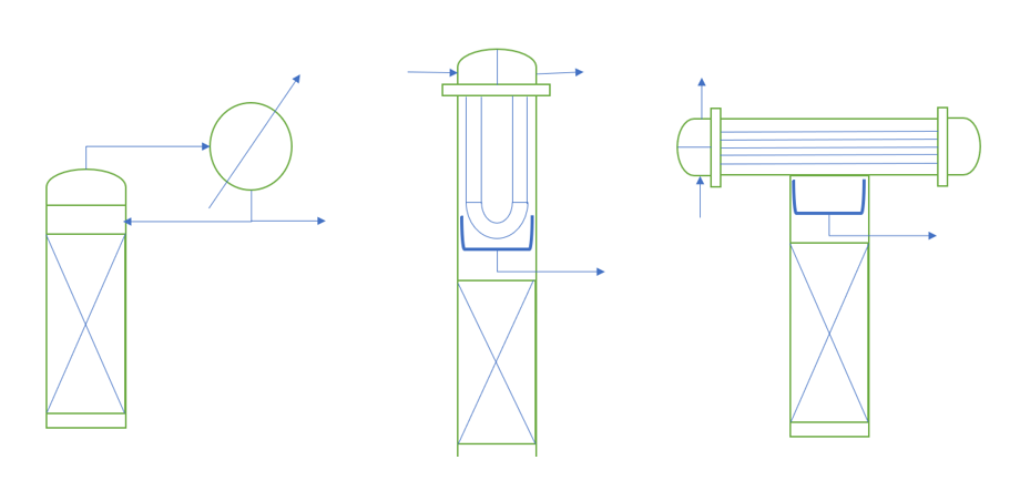
Among above options, first option we find is most common in industries. While other two options are good for the compounds which solidify at sub-cooling. In such cases, this type of condenser installation ensure the condensation at saturation temperature. Which avoids the sub-cooling of the condensate. We draw the product from liquid collection tray, while excess liquid overflows as reflux into the column.
Reflux Vessel
In batch distillation column we can provide reflux by gravity providing overhead condenser or by reflux pump. Using reflux vessel & pump gives us better control for reflux controlling. Simultaneously we can afford to install condenser at lower elevation also, which save power cost of cooling water pumping.
Precut, Intercut and Pure Cut Collection Vessels
As this is the batch distillation column setup and during distillation, we need to analyze samples. Therefore, till the sample analysis is confirming the requirement we need to hold the material before transferring it to respective tanks. Generally, in all batch distillation we generate precut collection which comes first. After this intercut comes which we collect into intercut vessel. And, finally pure cut comes which goes into the pure cut vessel. Subsequently these different cuts transferred into their respective tanks. This transfer into the tanks we do after confirming lab analysis results. If any cut goes beyond specification, we recycle it back into the batch distillation charging tank. Which we charge again in next batch distillation cycle. However this reprocessing is the additional cost for product manufacturing, which we must avoid.
Batch Distillation Operation Philosophy
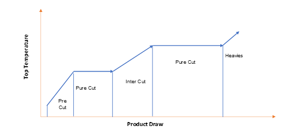
In distillation process top temperature is the proxy variable for purity of various components in kettle mixture. For example, let us assume a mixture contains low boiler, component ‘A’, component ‘B’ and heavy boilers. During distillation process, we can draw a line plot between column top temperature and product draw something like in Figure 4.0.
In starting of batch, we distill pre-cut which contains mostly low boilers and traces of ‘A’. The temperature keeps on increasing till we achieve the saturation temperature of pure ‘A’. During draw of component ‘A’ temperature remains constant. After distilling off component ‘A’ again top temperature start increase till we achieve the saturation temperature of pure component ‘B’. Till the purity of component ‘B’ is achieved we collect the inter cut, which is the mixture of ‘A‘ & ‘B‘. After recovery of component ‘B’, remaining bottom heavies with traces of component ‘B‘ is transferred into residue tank.
The batch distillation is also known by Rectification or Fractionation. During distillation we keep reflux constant while a particular cut or faction is distilled off (within a given temperature range). For the component’s mixture having closed boiling points during fractionation, reflux ratio is usually increasing to achieve desired distillated quality.
You will find batch columns either operating in TR / TP mode or continuous reflux mode. TR / TP stands for Total Reflux and Total Product. For example if your required reflux is 1 : 10 than you column will be running 10 minutes at TR (i.e., no distillate draw) and for 1 minutes will run at TP (i.e., no reflux only product draw). For the control of this sequence, we use a timer switch. Which operates a tree-way on-off solenoid operated valve. In case of continuous reflux mode, top temperature is in cascade with the reflux flow control valve. In this mode reflux flow and distillate flow control operate simultaneously.
Batch Distillation Column Process & Controls
As you can see Figure 1.0, shows a typical batch distillation column setup. To run a batch distillation column, first we charge the known quantity of mixture into the batch kettle. We collect the sample of this kettle charge to know the composition of various components. After this sequence of steps in process operation are as below:
- Close the vent of batch kettle, line up the cooling water in condenser and chilled water in vent condenser.
- If this is under vacuum operation line up the vacuum ejector or vacuum pump and apply desired vacuum. Drain the steam condensate from reboiler and start heating of batch kettle charge.
- Heating should be at slow rate to avoid any hammering in batch kettle. Keep the column at total reflux mode. Or in other words, we close the reflux vessel level control valve in starting.
- When boil up starts vapor goes into the condenser and after condensation goes into the reflux vessel. When there is 50% level in reflux vessel line up the reflux pump and start refluxing. Put the reboiler steam and reflux flow rate in auto mode (i.e., enter setpoint values as per SOP in DCS controller).
- When column temperature profile is stable start withdrawing precut by opening reflux pot level control valve. Put the reflux pot level control valve into auto mode. And, enter 50% setpoint in reflux pot level controller.
- When temperature of component ‘A‘ is reached as shown in Figure 2.0 stop precut draw and check the sample. During this period column will be running at total reflux. If sample analysis is confirming the requirement, start drawing pure component ‘A‘ in pure cut vessel.
- During withdrawing pure component, all the control valves (i.e., steam flow, reflux flow and reflux pot level control valves) will be in auto mode. Reflux control should be in cascade control with column top temperature to ensure component purity. In this process component ‘A‘ concentration will deplete continuously in kettle charge and component ‘B‘ will start lifting with first component. Therefore, reflux will also continuously increase to maintain the purity of first component. After collection of the components ‘A‘ stop draw in pure cut vessel and line up draw into the intercut vessel.
- Again, repeat the step 6 and 7 for component ‘B‘ fractionation. After completion of second component distillation, stop heating to the reboiler. And, finally we transfer the bottom mass into residue tank through a cooler.
Process Design Considerations
Batch column design depends on batch cycle time for the complete distillation process. Batch cycle time includes time required in all the steps, from kettle charging to leftover transfer. During batch distillation, components having close boiling points are difficult to separate and require higher reflux ratio in given column. This leads to high collection time & increases the overall batch cycle time. During design we need to optimize column diameter and column height to minimize the batch cycle time. In other words, this is the optimization between fixed cost v/s variable cost.
Process design for column diameter & stages depends on that fraction collection step, which has highest liquid and vapor loading. Simultaneous we estimate the area of reboiler and condenser accordingly. For the reboiler design pressure must be based on the end of batch temperature & pressure conditions. Because at the end of batch, kettle temperature will be highest, therefore in case of steam in reboiler saturation steam pressure will be highest. Similarly, for condenser log mean temperature difference (LMTD) will be lowest in starting and highest in end of the batch. So, keeping this LMTD effect in mind condenser sizing should be done.
In nut shell we can say column diameter & height estimation, reboiler & condenser sizing must be designed based on highest process requirements. Otherwise it will increase the distillation batch cycle time.
Conclusion
You can see batch distillation process is dynamic in nature in contrast to continuous distillation process. Continuous distillation is a steady state process and has strict controls. In batch distillation process operating parameters keeps on changing as distillation progress forward. This is because batch kettle composition is changing continuously. Therefore, a dynamic modeling of the batch distillation will be very helpful in optimizing the process. This modeling can help you to minimize the batch cycle time. Which will increase the plant productivity and reduce energy cost also.
Digital transformation and real time data analytics will give insight in the process. Which will minimize the batch to batch variations in batch cycle time. Predictive analysis can reduce the sample analysis requirement, which is the cause of productivity loss because of waiting time for analysis. Moreover, will avoid the sample analysis cost also. In many cases where batches fail during distillation, machine learning models can derive artificial intelligence for prediction in advance. This way AI (artificial intelligence) can help to prevent the batch failure, which can avoid huge revenue loss to the business.
Thanks for reading and looking forward for your comments.