As we all know shell & tube heat exchanger is the equipment, which we use to exchange heat between two streams available at different temperature. In this type of exchanger, one side we know as shell side and other we call the tube side. In a heat exchanger heat transfer between streams can be of two type, which as below:
- Sensible heat transfer – it means there is no change in phases of both side of streams. In other words, stream combination can be liquid-liquid, gas-liquid or gas-gas, without any phase change. Examples of this type of heat exchanger are Coolers, Chillers, Pre-heaters, etc.
- Latent heat transfer – here during heat transfer between the streams phase change takes place (i.e., evaporation and condensation process). The heat exchanger examples for this category are Condensers, Reboilers, Evaporators, etc.
However, in condensation and evaporation process we can see the combined effect of above both type of heat transfer mechanisms.
During basic design engineering a Process Engineer is supposed to do the design of heat exchangers and need to prepare a specification data sheet also. Subsequently, this Process Data Sheet of heat exchanger is given to mechanical engineer or the equipment fabricator to perform mechanical design of the equipment.
Therefore, in this article we will discuss the Process Data Sheet (PDS) of a Shell & Tube Heat Exchanger. This will help you to prepare the heat exchanger specification sheet properly.
Table of Contents
Data Sheet Format
For a process engineer it is very important that heat exchanger data sheet is correct and complete. As, this will be the base document for detail engineering and quotation subscription of the heat exchanger. Any flaw in this document will lead to inefficient and wrong design of the heat exchanger.
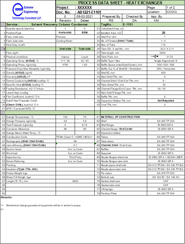
So, to start our discussion let us go through the below format of a Shell & Tube Exchanger PDS. Here, you can see different sections which includes information or data required for the design of a heat exchanger. Let us discuss each section one by one.
Top Header
This includes identification details of the process data sheet or specification sheet. This information includes, the logo and name of your organization. Heat exchanger description, tag number and project name are very important during erection work. As, this helps the people at site for easy and errorfree identification of that heat exchanger and correct installation.
Other details are document number, revision number which are important from documentation point of view. Apart from this, details of maker, checker and approver are important to trace the engineers involved in this project. Also, information for which this PDS we are issuing is important like, it can be “Issued for Inquiry” or “Issued for Comments” etc.
TEMA Standards for Shell & Tube Exchanger
There are three classes of mechanical standards in TEMA are Classes R, C, and B. Which represents varying degrees of mechanical details for the criticality of respective process plant. According to this, the code designations for mechanical design and fabrication are as below:
RCB TEMA Classes includes all classes of construction/design and are identical; shell diameter (inside) not exceeding 150 cm, and maximum design pressure of 200 bar.
TEMA Class R designates severe requirements of petroleum and other related processing applications.
For moderate requirements of commercial and general process applications TEMA Class C is followed.
In case of specifies design and fabrication for chemical process service, we use TEMA Class C. And, this is the standard which we can see widely used in chemical process industries.
GMP or Good Manufacturing Practice, includes topics outside the scope of the basic standards. This is the standard which is customized for specific requirement, generally non-critical services.
As we know shell and tube heat exchangers can be identified by front head type, shell type, and rear head type. For this you can refer to below table, from the Standards of Tubular Exchanger Manufacturers Association (TEMA).
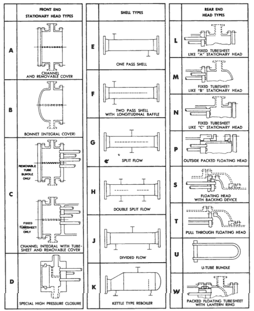
In above data sheet, heat exchanger is horizontal and TEMA type is BEM.
Operating & Mechanical Data
In this section you need to mention operating and design data for the heat exchanger. First, we provide fluid names, flow rates and its physical condition (i.e., liquid, vapor, gas) at both side of the exchanger.
Next, we mention physical properties of both side fluid at average temperature includes like, fluid density, viscosity, thermal conductivity, surface tension, specific heat, latent heat, etc. Other than this we provide fouling resistances and allowable pressure drop at both side of the heat exchanger.
Operating pressure & temperature, design pressure & temperature are required to select the material allowable stress for thickness calculations. Apart from this we need to mention equivalent hydrotest or pneumatic test pressure for the final equipment testing purpose.
Moreover, tube side parameters include number of tubes, number of tube pass, tube diameter, tube length, tube pitch, etc. And, for shell side baffle type, number of baffles, baffle cut, baffle spacing, tube bundle diameter, etc. information is important.
Various mechanical data comprises, corrosion allowance (around 1.6mm for MS and Nil for SS), insulation thickness & type. The mechanical design is done based on above data and exchanger mechanical details are calculated. This includes details such as thickness for shell and dish ends, tube sheet thickness, body flange thickness & bolt size, tube type and thickness, etc.
Other Codes and Standards
You need to mention the heat exchanger design code like, TEMA Class type, ASME or GEP (Good Engineering Practices). Other than this you need to mention stress reliving requirement codes, if required. Also, details of joint efficiency and radiography should be provided. Joint efficiency for critical equipment should be 100%, while for other moderate and non-critical services it can be 85% and 70% respectively. Among these 70% is the lowest joint efficiency and required minimum shell and channel cover thickness. This joint efficiency we consider for non-critical services.
Sketch of the Heat Exchanger
You should provide schematic drawing of the heat exchanger. This information helps user to understand the geometry and installation details of the equipment. The various information we provide in sketch includes heat exchanger type & orientation, nozzles with location, support type, etc.
Material of Construction (MOC)
In this section we provide the information regarding MOC of various part of the heat exchanger. As you can see in sketch a shell & tube heat exchanger can be divided in mainly two parts first is tube side and second shell side. The MOC of each side depends on their respective fluid properties and design temperature, pressure conditions.
Different parts on tube side are like tubes, tube sheet, channel covers with flanges, partition plate and nozzle pipe and flanges. While on shell side it comprises main shell, tube sheet, baffle plates, tie rods, nozzle pipe and flanges, etc.
Moreover MOC for exchanger support, nozzle pad plates, lifting lugs, fasteners and gaskets we need to provide in this data sheet.
For the economical design you can select lined body flanges also. Here you can fabricate large size body flanges of MS having Stainless Steel (SS).
We use material compatibility chart to find the suitable metallurgy for the heat exchanger fabrication. Moreover, in special material situation we need to conduct coupon material test, to find best compatible material.
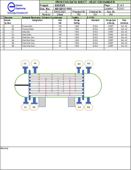
Nozzle Schedule
Here we provide details for all the nozzles required in heat exchanger. Commonly in every exchanger we require, Tube side inlet/outlet nozzle, shell side inlet/outlet nozzles, vent and drain nozzles at both sides, for some cases where installation is under pressure, we need safety valve nozzle also.
In nozzle details we provide the standards to follow (i.e., ASME/ANSI or BIS) for flange dimensions. Moreover, we need to mention nozzle pipe schedule & thickness with flange ratings. Also, nozzle tag number and quantity of nozzles is there in the table.
Remarks
In this section we can provide miscellaneous information, which are common. Based on your specific requirements this information can be customized. Whole purpose here is to provide all general clarification to the fabricator or user, also these are important for the performance and long service life of a exchanger.
Use of Shell & Tube type Heat Exchanger
Based on the application of shell & tube exchanger, we call them by various names, these are as described below:
Condenser
We use condensers to condense the distillation column vapor using cooling water circulation. Generally, in condenser process fluid is in shell side and cooling water which has fouling tendency remain tube side. Moreover, a condenser can be total or partial, in total condenser incoming vapor condenses completely and condensed liquid is subcooled most of the time. While in partial condenser we condense part of the vapor to meet the reflux requirement and recover top product in gas phase.
We use partial condensers where required condensing temperature is very low at column operating pressure. For example, in case of ammonia recovery distillation column. Where for total condensation of pure ammonia gas required temperature is (-)33 0C. In this case we can use partial condensation @ 3.5 bar column operating pressure. After partial condensation, aqueous ammonia will go for reflux and ammonia will be recovered as a product in gas form.
Reboiler
In distillation column we use reboiler to supply heat. And, reboiler can be many types like, vertical thermosyphon, kettle type or forced circulation. For fouling services, we go for kettle type reboilers or forced circulation type reboilers. However, vertical thermosyphon reboilers are widely used reboilers in chemical process industries.
Chillers
We use chillers to cool down the process using chilled water or brine. In this process is generally in shell side, while utility is tube side.
Coolers
Similar to chillers, only difference cooling utility is the water. We use coolers to cool the process fluid or hot stream using cooling water.
Evaporator
This type of shell & tube exchangers we use in multiple effect evaporators. In this process fluid is generally aqueous solution of a salt or non-volatile miscible compound. Process fluid is in tube side and which circulates either because of natural thermosyphon or using circulation pump. Shell side there is condensing steam which supply heat for water evaporation and concentrate the outgoing fluid.
Pre-Heater
We use preheater, to preheat a stream using steam or other heating utility.
Conclusion
This article will help to understand and prepare a process data sheet for a shell & tube heat exchanger. A new process engineer can take guidance from here and can prepare a complete and perfect process data sheet. This basic engineering document we provide to mechanical design engineer to design and detailing purpose. Moreover, we can send the PDS to the equipment fabricators directly for subscribing equipment fabrication quotations.
Thanks for your reading and looking forward for the comments.