In many chemical manufacturing processes ammonia is used as a raw material and generally feed in excess than theoretical requirement. And unconverted ammonia recovery is very important for the lower product cost and market competitiveness. In this type of process, we first absorb this unconverted ammonia in the absorber column it can be packed or tray type. In ammonia absorber column, water is used to absorb the unconverted ammonia from outgoing product off gases. From ammonia absorber column bottom we get aqueous ammonia solution. This aqueous ammonia solution contains around 16 – 20 wt.% ammonia. The concentration of ammonia in absorber column bottom depends on absorber column temperature and other water-soluble components present in feed stream.
Table of Contents
Process Details for Ammonia Recovery Column
You can refer to below figure to understand a typical ammonia recovery system. In this we have a distillation column which can be packed or tray type. This column operates at pressure around 5.0 bar, steam is supplied from reboiler and at top there is a partial condenser. Cooling water supply temperature is 32 0C. And @ 5.0 bar column vapour temperature will be around 75 – 78 0C. In partial condenser, partially condensed column vapour goes for reflux. And pure ammonia is recovered and recycle back in gas phase from this condenser. In this distillation column, reboiler can be natural thermosyphon or forced circulation type.
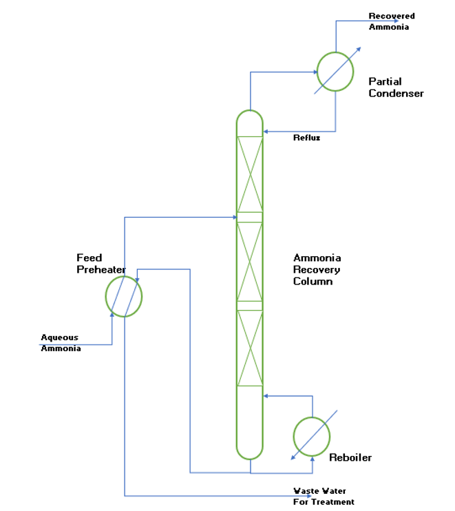
From above process flow diagram, you can understand the process of a typical ammonia recovery column. Aqueous ammonia feed from ammonia absorber enters into the ammonia recovery column via a feed preheater. In feed preheater we use waste heat of hot bottom outlet stream from ammonia recovery column to preheat the column feed. From reboiler heat is supplied to column; we use saturated steam in reboiler as a heating utility.
Column operates at 5.0 bar pressure and column top goes into a partial condenser. In partial condenser part of the vapor condense and goes as a reflux into the column. While ammonia gas recycle back to the process. In case of excess moisture carryover in recovered ammonia, you can provide a chiller. This chiller will condense the excess water content in recovered ammonia and recovered ammonia concentration will increase. The condensed water in form of ammonical solution goes back as reflux into the column.
Column bottom, which contains traces of ammonia and other impurities is sent for effluent treatment plant.
Material Balance of Ammonia Recovery Column
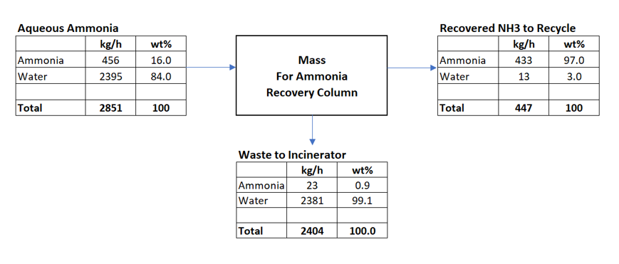
To design the ammonia recovery process, we will consider below material balance. This I have taken from my earlier article, “Process Design Calculations for Ammonia Absorber”. We are feeding 16 wt.% ammonia water solution into the ammonia recovery column. This column will operate at 5.0 bar pressure. The column recovers around 95% of ammonia from top and concentration is 97 wt.%. Bottom of column is a waste water stream contains <1.0 wt.% ammonia. In reboiler we will use 9.0 bar saturated steam for column heating and in partial condenser we will use cooling water at 32 0C supply temperature.
Heat Balance for Ammonia Recovery Process
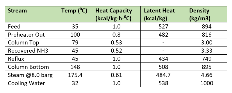
Now we will do the energy balance calculation for reboiler, partial condenser and feed preheater. Subsequently we will estimate the requirement of steam and cooling water also. For this purpose, below are the various parameters and properties.
Reflux rate is 71 kg/h, having 44 wt.% ammonia content. Now we can calculate the heat load on column reboiler at column bottom temperature (i.e., 148 0C) as reference.
Reboiler heat load, Qr = Feed rate*Heat capacity*(148 – 100) + Reflux rate*Latent heat + Reflux rate*Heat capacity*(148 – 45) + Recovered NH3*Heat of solution*ammonia concentration + Recovered NH3*Latent heat of water*moisture content
Qr = 2851*1.0*(148 – 100) + 71*434 + 71*1.0*(148 – 45) + 433*521*0.97 + 433*538*0.03
= 400798 kcal/h
Partial condenser heat load, Qc = Reflux rate*Latent heat + Reflux rate*Heat capacity*(79 – 45) + Recovered ammonia*Heat capacity*(79 – 45)
Qc = 71*434 + 71*1.0*(79 – 45) + 433*0.52*(79 – 45) = 40883 kcal/h
Heat load on preheater, Qp = Bottom flow rate*Heat capacity*(148 – 71), after passing through feed preheater column bottom streams cools down to 71 0C.
Qp = 2404*1.0*(148 – 71) = 185108 kcal/h
We can calculate feed temperature after passing through feed preheater as below
T = Feed temperature at feed preheater inlet + Qp/Feed rate*Heat capacity
T = 35 + 185108/(2851*1.0) = 35 + 65 = 100 0C
Utility Requirement and Equipment Sizing
We will estimate the steam requirement for ammonia column reboiler.
Ms = Qr / Latent heat of steam @ 9bar = 400798/484.7 = 826.9 kg/h
With 5% heat loss, Ms’ = Ms*1.05 = 868 kg/h
Temperature difference for heat transfer = 175.4 – 148 = 27.4 0C
Over heat transfer for reboiler = 600 kcal/h-m2–0C
Estimated reboiler area, Areb = Qr/(600*27.4) = 400789/(600*27.4) = 24.4 m2
Taking 20% excess, reboiler area will be, Areb’ = 24.4*1.20 = 29.3 ~ 30 m2
For partial condenser we can calculate cooling water requirement as below. We will take Condenser cooling water outlet temperature at 38 0C.
Mc = Qc/(Heat capacity*(38 – 32) = 40883/(1.0*6) = 6814 kg/h
LMTD (Log mean temperature difference) = ((79-38) – (45-32))/ln((79-38)/(45-32)) = 24.4 0C
Overall heat transfer coefficient for partial condenser = 150 kcal/h-m2–0C
Estimated condenser area will be, Acon = Qc/(LMTD*150) = 40883/(24.4*150) = 11.2 m2
Taking 20% excess, condenser area will be, Acon’ = 11.2*1.20 = 13.44 ~ 15 m2
Feed preheater sizing we can do as follows. First let us calculate LMTD.
LMTD = ((148-100)-(71-35))/ln((148-100)/(71-35)) = 41.7 0C
Overall heat transfer coefficient for feed preheater = 350 kcal/h-m2–0C
Estimated feed preheater area will be, Aphe = Qp/(350*LMTD) = 185108/(350*41.7) = 12.7m2
Taking 20% excess, area will be, Aphe’ = 12.7*1.20 = 15.24 ~ 16 m2
Process Controls and Instrumentation
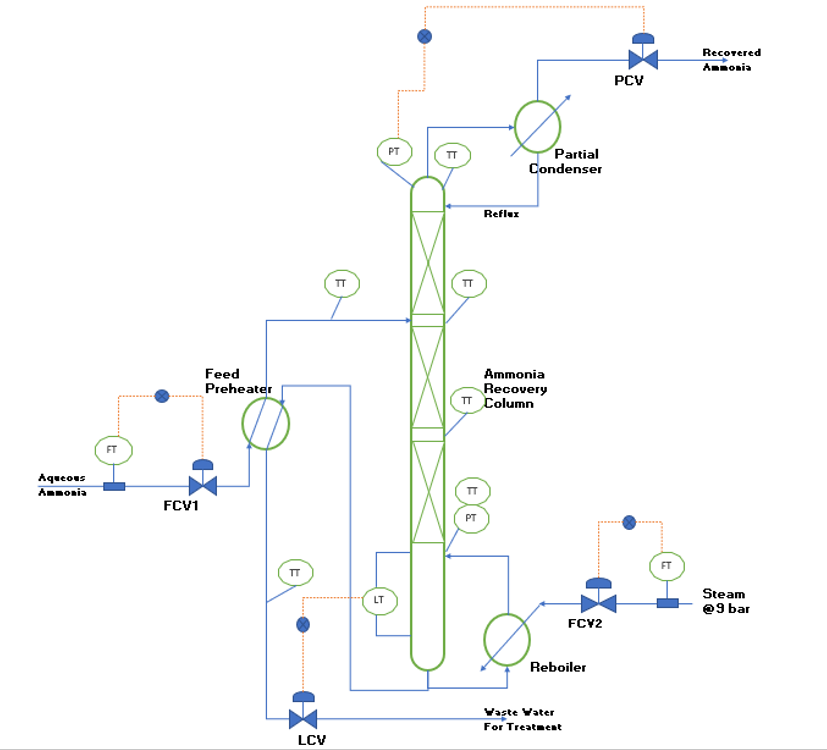
For stable and efficient operation of the ammonia recovery column we need to provide adequate instrumentation and controls. To understand this, you can refer the below figure.
FCV1 is for maintaining constant feed to the ammonia recovery column.
FCV2 will ensure the constant steam flow to the reboiler. Furthermore, we can provide ratio control between feed and steam feed for better controls.
LCV maintain constant level in column bottom. This is critical for stable reboiler operation.
PCV in recovered ammonia gas line will maintain the column pressure.
Remaining instruments like temperature transmitters and pressure transmitters with help us to monitor the performance of the column. In case of any abnormalities, we will get alarms from these transmitters. And we can take necessary actions to restore the process at normal operating conditions.
Conclusion
In this article we discussed the process design and operation of ammonia recovery column. We developed a PFD, material balance and energy balance for the process. Also, we estimated the steam and cooling water requirements for our process. Furthermore, we calculated the surface areas for reboiler, partial condenser and feed preheater.
Apart from this we discussed various instrumentations and controls required for the efficient and stable operation of column.
This article can help you to design the ammonia recovery system for your plant.
Thank you very much for your reading, if you need any other information and clarification feel free to write me.