In chemical process industries we use Fired Heater or Furnace to supply the heat at higher temperature levels. When I say high level, it means around greater than 500 0C. As we know other sources of heat supply are boiler, thermic fluid heater and molten salt heating systems. Out of these boiler and thermic fluid heating system are most widely used in our industries. We will discuss comparative study of various heating options subsequently in this article.
Below are two commonly seen designs of furnace for most process services. First is Vertical Cylindrical Furnace which we use for low heat duty around less than 100 MBtu/hr. Second one is Horizontal Tube Cabin Type Furnace; this we use for higher duties say in the range around 100 – 450 MBtu/hr.
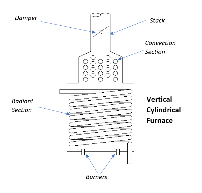
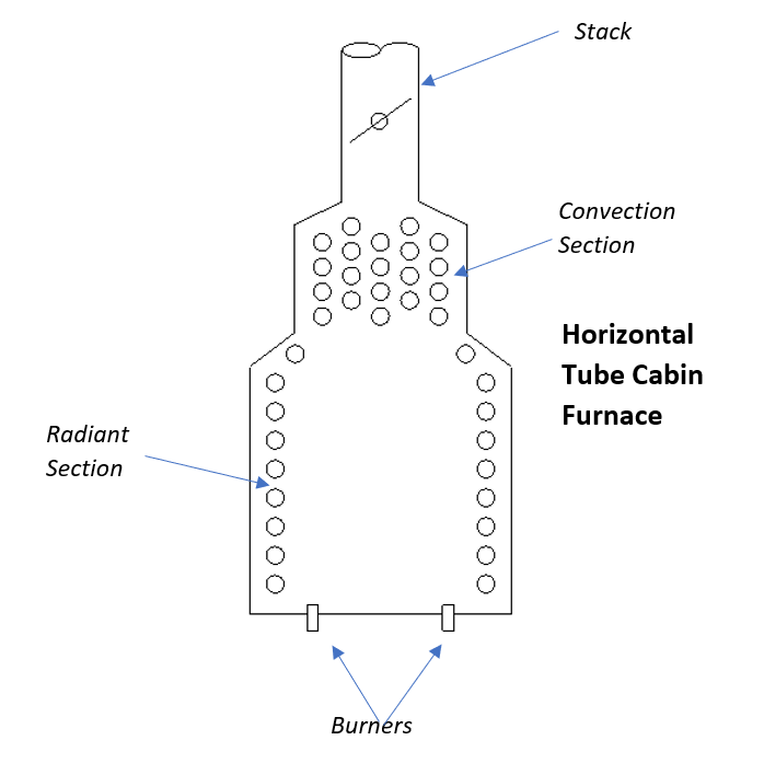
Table of Contents
Various Heat Supply Systems
As I mentioned above, in chemical industries we can supply heat to the process using steam from boilers, thermic fluid heater, molten salt system and fired heater mainly. For selection, we take into consideration the design parameters such as temperature levels, heat transfer efficiency, pumping power and operational life. We need to look into the performance of the fluid and operating expenses. Also, we can’t overlook other factors like safety parameters such as pressure build-up, flashpoint, flammability and toxicity. With these concerns in mind, you can select better option among various alternatives as mentioned above. Let us discuss all of them one by one.
Boilers
Boilers are used in almost all process industries as a source of heating utility. Boiler generates steam which we use to supply heat to reboilers, evaporators, heaters etc. In case of steam, as heating temperature increases required operating pressure of the boiler and process equipment goes up.
For example, if we want to supply heat at 150 0C to a distillation column through reboiler. The require steam pressure is around 16 bar (as we need steam temperature between 190 – 200 0C). Therefore, for higher process temperature say 230 0C, we need much higher pressure (i.e., around 50 bar pressure saturated steam). For this pressure, we require higher thickness of shell, tube-sheet, flanges, tubes, nozzles, piping, etc. This will increase equipment cost and moreover possibility of hazardous will be too high.
Therefore, for heating up to 170 0C, steam is used in our industries (as required steam pressure is around 16 bar). And, for higher temperature heating requirements, it is better to use thermic fluid system from economy and safety point of view.
Thermic Fluid Heating System
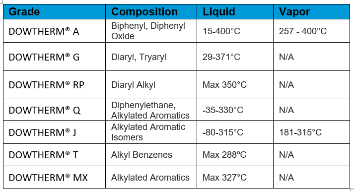
In case of heating requirements between 170 – 360 0C, we generally use thermic fluid system. Based on the operating temperature requirement, we decide the types of thermic fluid. Below table can give you the details based on the temperature requirement. For heat supply to thermic fluid, we use furnace oil, natural gas, electric heater or coal.
Molten Salt Heating System
For the temperature services higher than 360 0C, we can use molten salt heating system. As thermic fluid degrades rapidly and we need regular replacement to maintain its properties. Therefore, heating with thermic fluid becomes uneconomical. In this case we can use molten salt heaters for heating requirements, which is suitable up to 500 0C. One of the most commonly used molten salts is a eutectic mixture of sodium nitrate and potassium nitrate.
You need to provide proper heat tracing to avoid molten salt solidification problem.
Furnace or Fired Heater
Fired heater in process industries can supply heat at highest possible temperature requirements. This temperature depends on the maximum operating temperature limits of the material of construction. For example, in case of Ketene Furnace, acetic acid cracking takes place @ 740 0C. In ketene furnace we use tube material as Inconel, which has high melting points (i.e., > 1200 0C).
In a fired heater we can use different type of fuels like furnace oil, natural gas, coal etc. The process fluid enters into tube side of the furnace and fuel combustion takes place in furnace chamber. To minimize heat loss from furnace, we provide refractory lining inside and insulation outside of the furnace body.
In this article we will discuss furnace calculations in detail. Furthermore, we will discuss the automation and control for efficient and safe furnace operation. For this purpose, we will consider a furnace for air heating at 620 0C. This hot air we need for the reactor pre-heating and we will use furnace oil as a fuel.
Process Details for Furnace
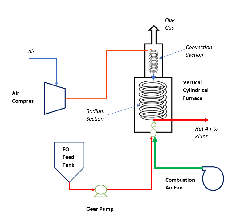
You can refer to below figure to understand the process. Here we are feeding process air for compressor to the furnace coil at inlet temperature 110 0C. This air first goes into the convection section and exchange heat with out going hot flue gases. After preheating air goes into the radiant section coils/tubes. The outlet temperature of hot process air from furnace is maintained at 620 0C. In furnace chamber bottom there are burners in which we feed furnace oil and combustion air. This mixture burns and supply heat to the process air, which is flowing through furnace coils.
Furnace Calculations
So, now we will do the calculations for furnace, which includes design basis, heat duty, theoretical air requirement, furnace efficiency, adiabatic flame temperature, etc.
Design Basis
Flow rate of process ai : 6000 kg/h
Compressor discharge pressure : 3.0 bar
Inlet temperature of air to the furnace : 110 0C
Heat capacity of process air : 0.25 kcal/kg-0C
Air discharge temperature from furnace : 620 0C
Flue gas discharge temperature : 285 0C
Flue gas heat capacity : 0.33 kcal/kg-0C
Furnace oil composition (% wt/wt)
Carbon : 85.8
H2 : 12.4
N2 : 0.5
S : 0.5
Gross Calorific Value : 10800 kcal/kg
Net Calorific Value : 10197 kcal/kg
Furnace thermal efficiency : 80%
Heat Load on Furnace
You can calculate heat load on furnace from the heating requirement of process air.
Q = Air flow rate*Heat Capacity*(620 – 110)
Q = 6000*0.25*(620 – 110) = 765,000 kcal/h
Considering 5% heat loss from furnace actual heat requirement will be Q’ = 765,000*1.05 = 803,250 kcal/h.
Furnace Oil Requirement, Mf = Heat load on furnace/(FO Net Calorific Value*Furnace Efficiency)
Mf = 803,250/(10197*(80/100)) = 98.5 kg/h
Theoretical Air Requirement
Now we can calculate the theoretical air required for Mf = 98.5 kg/h furnace oil firing, using furnace oil composition. Below are combustion equations for various fuel constituents.
C + O2 = CO2
H2 + 0.5O2 = H2O
S + O2 = SO2
A_th = [(C/12)*32 + (H2/2)*0.5*32 + (S/32)*32]/0.23
A_th = [(98.5*0.858/12)*32 + (98.5*0.124/2)*0.5*32 + (98.5*0.05/32)*32]/0.23 = 1426 kg/h
Taking 20% excess air, actual air for combustion will be, Aa = 1426*1.20 = 1711 kg/h
Furnace Efficiency Estimation
Since, we have furnace oil feed rate, net calorific value and combustion air flow rate with us. Assuming 100% burner efficiency.
So, generation of heat from furnace oil firing, Q1 = 98.5*10197 = 1,004,404 kcal/h
Heat loss from insulation to the surrounding (which is 5%), L1 = Q1*5/100 = 50,220 kcal/h
Heat loss with furnace flue gases, L2 = (1711 + 98.5)*0.33*(285 – 35) = 149,284 kcal/h
(here we have assumed combustion air supply temperature 35 0C and total flue gas flow is furnace oils flow rate + actual air flow rate)
So, Furnace Efficiency, Eff = (Q1 – L1 – L2)*100/Q1 = (1,004,404-50,220-149,284)*100/1,004,404 = 80%
Adiabatic Flame Temperature Calculation
Since you have fuel burning rate and actual combustion air flow, so adiabatic flame temperature can be estimated as follows:
Adiabatic Flame Temperature, Taf = 35 + FO feed rate*FO NCV/(Flue gas flow rate*Heat Capacity)
Adiabatic Flame Temperature, Taf = 35 + 98.5*10197/((1711+98.5)*0.33) = 35 + 1682 = 1717 0C
In furnace around 45% of total heat is comprises by radiative heat, therefore heat absorbed by process air in radiant section will be, Qr = Q1*0.45 = 1,004,404*0.45 = 451,982 kcal/h
Now balance heat going into convection section will be, Qc = Q1 – Qr = 552,422 kcal/h
Now we can calculate the flue gas temperature leaving from the radiant section of the furnace as below,
Flue gas temperature at convection section inlet, Tci = Taf – Qr/(Flue gas flow rate*Heat Capacity)
Flue gas temperature at convection section inlet, Tci = 1717 – 451,982/((1711-98.5)*0.33) = 868 0C In summary we can see that, in radiant section of furnace around 451,982 kcal/h heat is absorbed by process air. Before entering into the radiant section process air pre-heat in convection section by exchanging heat from flue gases. In other words, hot flue gas cools down from 868 0C to 285 0C to pre-heat the process air.
Fired Heater Instrumentation & Control
Hence, from above discussion you could have understand that, to operate a furnace efficiently and safely we need proper instrumentation and controls. Otherwise in the absence of automation furnace efficiency will be reducing and may lead to possible process hazard also. When we talk about process hazardous it means like, furnace backfire, explosion in body, flare at furnace stack outlet, burning of furnace tubes, etc.
So, you can refer below figure to understand various instrumentation and controls for a safe and efficient furnace operation.
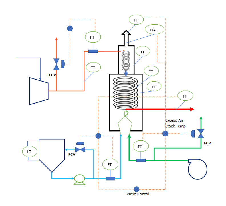
To control furnace oil flow rate, we use FCV in furnace oil feed bypass line. Apart from this the fuel flow rate should be in cascade control to maintain the furnace process air outlet temperature. Moreover, level transmitter shows us the furnace oil inventory in feed tank.
Combustion air flow control require a control valve in vent line at the discharge of combustion air fan. This controller is very important for efficient and safe furnace operation. We should provide a ratio control with the fuel feed flow. If there is change in fuel flow the combustion air flow will change accordingly.
Other important controls are stake temperature and excess air control. If these values go beyond set point combustion air flow control valve will take action to control them. To measure excess air in flue gas we provide oxygen analyser in furnace stack.
Other instruments like PT gives the back-pressure indication at furnace inlet. Various temperatures transmitters we need to monitor the radiant section, tube skin, convection section temperatures. These parameters are very critical for the furnace safety.
Discussion
In this article we discussed about various heat supply sources in our industries. Also, we did comparative study of all the options. Subsequently, we did process calculation for a process air pre-heating furnace. Furthermore, we discussed required instrumentation and process controls for the furnace.
Finally, I suggest you should look into the digital transformation of the fired heater also. In our industry furnace or fired heater is one of the highest energy consuming unit operation. Therefore, precise process control will be the key for cost effective and safe operation.
Digital transformation of the furnace will enable us to analyze the real time furnace parameters. Realtime monitoring of various critical parameters like stake temperature, oxygen % in furnace stack, process outlet temperature, furnace temperature, will give us insight in the furnace process. We can use this real time analysis to take timely decision to control the various parameters. This way we can maintain sustained efficiency at highest possible level.
We can also look into machine learning model to predict the furnace coil fouling or chocking problems. Moreover, in many processes frequent furnace tube failure takes place. In such cases we can use real time analytics and machine learning to predict the tube failure/leakages. This way, it will help us to take preventive steps to avoid furnace breakdowns. These sudden breakdowns cause plant shutdown, which is a huge revenue loss for any organization.
Thanks for reading and looking forward for your feedback and comments.