In chemical process industries we use vessels for handling fluids. This fluid can be liquid, solid, gas or combination of these. We need vessels for many purposes like, feeding or dozing, holding the material, collection of material, separation of the material, etc.
Based on the process requirements the geometry and orientation of these vessels can be various types. When we talk about geometry, main body can be cylindrical, rectangular, spherical. While, ends of the vessel in case of cylindrical can be ellipsoidal, hemispherical, spherical, conical or flat.
In this article we will discuss the vessel specification sheet. Also, we will discuss of different types of the vessels.
Process Data Sheet (PDS) is a very important document for process engineering. This is the part of Basic Design Engineering package. You need to understand, a correct and complete data sheet makes detail engineering work very easy and fast.
So, to get the insight about vessel PDS, let us go through the below format.
Table of Contents
Format of Vessel Specification Sheet
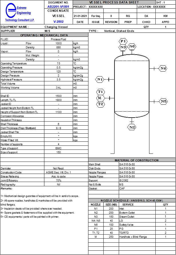
Below is the typical process data sheet format for a vessel. It contains following main sections.
Top Header
This includes the identification of the vessel data sheet or vessel specification sheet. You should put the logo and name of your organization. Vessel description, tag number and project name are very important during erection work. As, this helps the people at site for easy and error free identification of that vessel.
Other details are document number, revision number which are important from documentation point of view. Apart from this, details of maker, checker and approver are important to trace the engineers involved in this project. Also, information for which this PDS we are issuing is important like, it can be “Issued for Inquiry” or “Issued for Comments” etc. Moreover, we need to mention the geometry of the vessel (i.e., vertical, cylindrical, dished end, etc.).
Operating & Mechanical Data
In this section you need to mention operating and design data for the vessel. This information includes like, fluid details (i.e., composition), flow rate, fluid density, operating pressure & temperature, design pressure & temperature. Apart from this we need to mention equivalent hydrotest or pneumatic test pressure for the vessel.
Other process parameter includes vessel diameter and TL-TL height or length. Here TL means tangent line point of the dish end. Provide the total volume and working volume for the vessel. As a thumb rule we consider 80% working volume of the total vessel volume. Also, we should mention whether this is a jacketed vessel or not. If yes then provide the details for jacket dimension as well.
Various mechanical data comprises, corrosion allowance (around 1.6mm for MS and Nil for SS), insulation thickness & type. You need to mention thickness for shell, jacket and dish ends; however, fabricator can also calculate this based on your operating data.
Download Vessel Specification Sheet
Other mechanical data includes, empty and filled vessel weight. Type of vessel support like, legs, skirt, saddle or brackets. Demister pad requirement in case of knock out pots.
Other Codes and Standards
You need to mention the vessel design code like, ASME or GEP (Good Engineering Practices). Other than this you need to mention stress reliving requirement codes, if required. Also, details of joint efficiency and radiography should be provided. Joint efficiency for critical equipment should be 100%, while for other moderate and non-critical services it can be 85% and 70% respectively. Among these 70% is the lowest joint efficiency and required minimum vessel thickness. This joint efficiency we consider for non-critical services.
Sketch of the Vessel
You should provide schematic drawing of the vessel. This information helps user to understand the geometry and installation details. The various information we provide in sketch includes vessel type, nozzles with location, support type, etc.
Material of Construction (MOC)
In this section we provide the information regarding MOC of various part of the vessel. As you can see in sketch a vessel can be divided in different parts like Main Shell, Dish Ends, Nozzle Flanges, Nozzle Pipes, Support, Nuts & Bolts, Gaskets, etc.
For the economical vessel design you can select lined vessel also. Here you can fabricate MS vessel having Stainless Steel (SS) lining inside the vessel.
Material of construction depends on the fluid corrosive properties, erosive nature for handling slurries & pneumatic conveying, operating temperature and pressure. In chemical process industries you can find vessel MOC of Mild Steel, Stainless Steel, Inconel, Hastelloy etc. In case of non-metal construction MOC can be PP, PP-FRP, PVDF, HDPE etc. Apart from this we can have rubber lined vessel also in case of dilute sulfuric acid service.
We use material compatibility chart to find the suitable metallurgy for our vessel. Moreover, in special material situation we need to conduct coupon material test, to find best compatible material.
Nozzle Schedule
Here we provide details for all the nozzles required in vessel. Commonly in every vessel we require, Inlet Nozzle, Outlet Nozzle, Vent Nozzle, Manhole (in case of large diameter vessel > 1.50 m), Handhole, Drain point, Level gauge & level indicator nozzles, safety valve nozzle, temperature and pressure indicator nozzles.
Other then this many times we require light glass & sight glass nozzles also. In nozzle details we provide the standards to follow (i.e., ASME/ANSI or BIS) for flange dimensions.
Moreover, we need to mention nozzle pipe schedule & thickness with flange ratings. Also, nozzle tag number and quantity of nozzles is there in the table.
Remarks
In this section we can provide miscellaneous information, which are common. You can see in above format there are sample comments for your reference. Based on your specific requirements this information can be customized. Whole purpose here is to provide all the general clarification to the fabricator or user.
Sizing Guidelines for Vessels
Capacity of a vessel depends on volume of the material which we want to hold in that. In case of batch mode vessel size is, V (Total) = working volume/0.70.
For continuous operation we need to consider input volumetric flowrate and required holding time for the fluid. For example, let us assume flow rate is 0.10 m3/min and required holding time is 20 minutes then required vessel volume can be, V (Total) = (0.10 * 20)/0.70 = 2.86 m3.
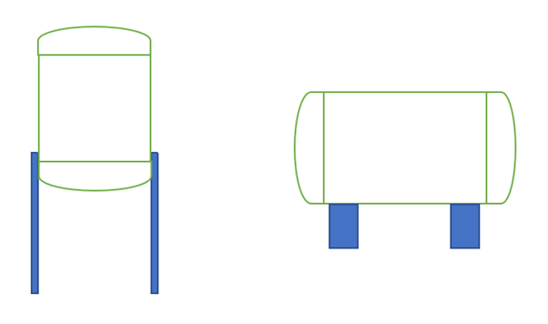
Most of the vertical vessel length to diameter ratio (L/D) is between 1.25 to 1.50. While for horizontal vessels we can consider larger L/D ratio say between 2.0 to 5.0.
Various types of Vessels
So far, we discussed about the PDS for vessel in detail. Below you can see different types of vessel we use in our plants.
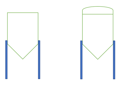
Vertical Top Flat or Dished and Bottom Conical
This type of vessel we use to handle slurry material in atmospheric pressure conditions. In case there is pressure inside the vessel, then we should use top dished and bottom conical vessel. Because for pressure conditions flat end thickness are higher then dished ends.
Bottom cone helps for settling of solids and we can take out relatively solid free liquid in pump suction for transfer of fluid. The thick slurry we can remove from bottom of the vessel.
Vertical and Horizontal Dished Ends
We use these two types of vessels most commonly in our plants. These are either vertical or horizontal and both ends are dished ends.
Thickness Calculation
We can estimate the plate thickness for shell plate and end plates as described below:
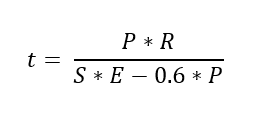
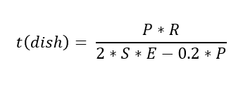
For estimating plate thickness of a cylindrical shell, you can use below equation
Ellipsoidal head thickness we can calculate using below equation
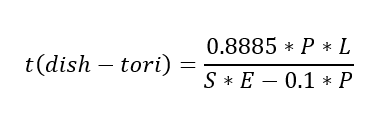
Tori-spherical dish head thickness we can estimate as follows
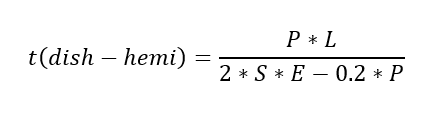
Hemi-spherical dish head thickness
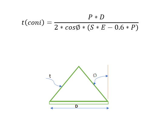
Conical head thickness you can estimate using below equation
Flat head thickness can be estimated by following equation
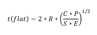
Look at UG-34 (assuming Section VIII, Division 1). C isn’t a constant factor of 0.33. Specifically look at C for welded covers and the increase in S by a factor of 1.5 so if you did use the yield stress your calculation is based on a number above yield.
In above equations various terms used are described as follows
t = thickness of plate, inch
P = design pressure, psi
S = allowable stress, psi
E = joint efficiency
R = inside radius of vessel, inch
D = inside diameter of head skirt or inside length of major axis of an ellipsoidal head, inch
L = inside radius of hemispherical head or inside crown radius of a tori-spherical head, inch
Conclusion
This article will help those new comer engineers, who are looking for the vessel specification sheet preparation. Using above guidelines, they will be able to deliver their documents timely and correctly.
Thanks for reading.