Batch plants are suitable for the products where production volumes are low. And in this we can produce different types of product with customized specifications. For example, multipurpose fine chemical plants, where we have many products to manufacture in single plant. Here product volume and specifications vary on regular basis as per customer’s requirement. Therefore, batch plants give us that flexibility in plant operation.
Batch plant has multiple process stages based on the product manufacturing requirements. Most commonly found stages in a batch plants are reaction, neutralization, filtration, solvent extraction, solvent recovery, batch distillation, crystallization, drying, packaging etc.
In this article we will discuss the process engineering steps of a batch plant. For this purpose we will take one hypothetical example. This plant includes two stages first reaction and second distillation.
Table of Contents
Reaction Details (Based on R&D Package)
Let us assume a homogeneous liquid phase non-catalytic reaction. In this reaction two organic raw materials, chemical ‘A’ and chemical ‘B’ reacts to form chemical ‘C’. This is an exothermic reaction and raw material ‘A’ is limiting reactant. Chemical ‘B’ consumption is 1.25 times of reactant ‘A’. Heat of reaction is 150 kcal/kg of reacted ‘A’.
In this process equilibrium conversion of the reaction is 85% on the mass basis for reactant ‘A’. This reaction takes place at 85 0C and atmospheric conditions. Selectivity of the reaction is 95% on mass basis. And remaining 5% of reacted ‘A’ converts into high boiling tar like material. This residue composition is as below which is sent for incineration. The calorific value for residue is 7500 kcal/kg approximately.
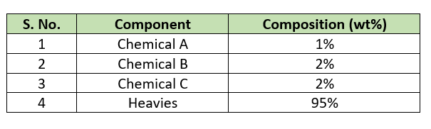
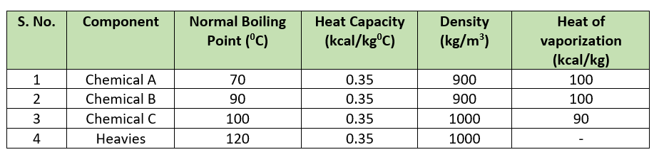
Physical and Chemical Properties
For our process calculations, we need physical and chemical properties for the chemicals are in below table.
A (liq.) + B (liq.) —-> C (liq.) at 85 0C and atmospheric pressure.
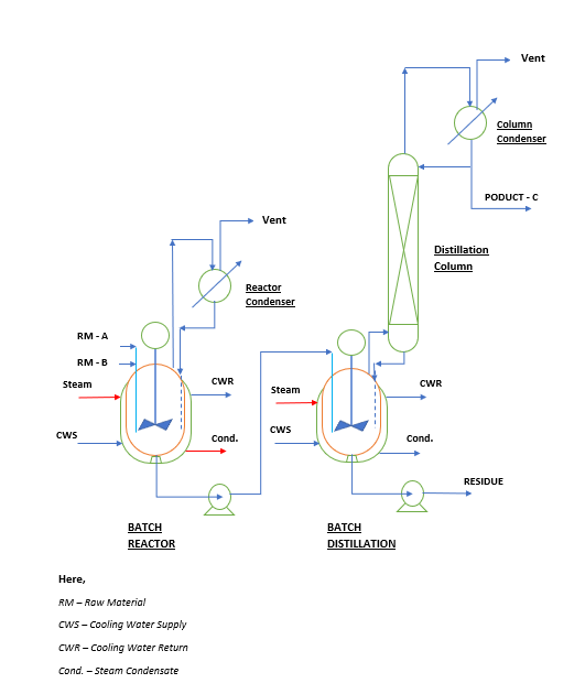
Process Flow Diagram (PFD)
Material Balance for the Plant
This process includes two steps first is reaction and second is distillation. The material balance for per batch will be as below.
- Charge of RM – A, 2000 kgs/batch
- Charge of RM – B, 2500 kgs/batch (since B is charged 1.25 times of A)
- Total mass of in reactor (RM – A + RM – B = 4500 kgs/batch)
- Equilibrium conversion is 85% hence unreacted RM – A in crude product = 2000*(100 – 85)/100 = 300 kg.
- Unreacted RM – B in crude will be = 300*1.25 =375 kg.
- Product C in crude will be (2000 + 2500) *0.85*0.95 = 3633 kg (since selectivity is 95% for the product C.)
- Heavies generation in reaction will be = (2000 + 2500) *0.85*0.05 = 181.7 kg/batch. Since the composition of heavies in residue is 95% hence residue generation per batch will be = 181.7 *100/95 = 191.3 kg.
- RM – A loss in residue will be 191.3 *1/100 = 1.91 kg/batch
- RM – B loss in residue will be 191.3 *2/100 = 3.83 kg/batch
- Loss of Product C in residue will be 191.3 *2/100 = 3.82 kg/batch
- The recovered quantities from distillation based on 90% recovery will be as below (given in R&D technology package).
- RM – A recovered = 300 *90/100 = 270 kg/batch
- RM – B recovered = 375 *90/100 = 337.5 kg/batch
- Product – C recovered = 3633 *90/100 = 3269.7 kg/batch
- Intercut quantity of A & B = 45.5 kg/batch (66% A and 34% B) – from package
- Intercut quantity of B & C = 44.0 kg/batch (50% B and 50% C) – from package
- Total production of product – C will be = product in crude – loss in intercut – loss in residue = 3633 – 22 – 3.82 = 3607.2 kg/batch.
- RM – A consumed = Charged – Recovered = 2000 – 270 = 1730 kg/batch
- Total RM – B consumed = 2500 – 337.5 = 2162.5 kg/batch
Energy Balance for the Batch
Heating utility for our process is 3.5 bar steam at saturated conditions. The temperature of the steam is 139 0C and latent heat is 513.5 kcal/kg.
Steam Requirement
- Heat load for reaction mass heating after charging of RM – B will be Q1 = mass RM-B * Cp * (initial temp – final temp) = 2500*0.35*(80-35) = 39375 kcal/batch. Hence steam requirement will be m1 = Q1/513.5 = 76.7 kg/batch.
- Heat load and steam requirement in distillation will as follows:
- For recovery of RM – A, heat load will be Q2 = mass recovered * (1 + reflux ratio) * latent heat = 270*(1 + 5)*100 = 162000 kcal/batch. Steam requirement will be m2 = Q2/513.5 = 162000/513.5 = 315.5 kg/batch.
- Similarly, for RM – B recovery Q3 = 337.5*(1 + 10)*100 = 371250 kcal/batch. Steam requirement will be m3 = Q3/513.5 = 723.0 kg/batch.
- For product recovery Q4 = 3269.7*(1 + 10)*90 = 3237003 kcal/batch. Steam requirement will be m4 = Q4/513.5 = 3237003/513.5 = 6303.8 kg/batch.
- For first intercut Q5 = 44.5*(1 + 25)*100 = 115700 kcal/batch. Steam required will be m5 = Q5/513.5 = 225.3 kg/batch.
- Heat load for second intercut Q6 = 44.0*(1 + 40)*100 = 180400 kcal/batch. Hence steam requirement will be m6 = Q6/513.5 = 351.3 kg/batch.
Therefore, total steam requirement for total batch processing will be Q = Q1 + Q2 + Q3 + Q4 + Q5 + Q6 = 76.7+315.5+723.0+6303.8+225.3+351.3 = 7995.6 kg/batch. Considering 5% steam loss actual steam requirement will be Q’ = 1.05*Q = 8395 kg/batch.
Cooling Water Requirement
Cooling water flow rate requirement will be based on when our reaction is going on and pure product draw is going on. As this will be maximum requirement any point of time during the process.
- Hence, heat load on jacket during reaction q1 = rate of addition A * heat of reaction = 500 * 150 = 7500 kcal/h (for calculation we are considering 100% conversion). Cooling water supply and return temperature are 32 and 40 0C respectively. Hence, cooling water flow will be w1 = q1/(Cpw*(40-32)) = 7500/(1*(40-32)) = 937.5 kg/h.
- Heat load during pure product draw (3269.7/10 = 327 kg/h) will be q2 = 327*(1 + 10) *90 = 323730 kcal/h. Therefore, cooling water requirement at column condenser will be w2 = q2/(Cpw*(40-32)) = 323730/(1*(40-32)) = 40466 kg/h.
- Water circulation in reactor condenser w3 = 5000 kg/h.
Total flow rate for cooling water pump will be W = w1 + w2 + w3= 937.5 + 40466 + 5000 = 46403.5 kg/h or 46.4 m3/h.
Power Requirement
Cooling water pump will be 50 m3/h and 30 m head. Hence, power consumption will be P1 = m*9.81*h/(3600*pump efficiency) = 50000*9.81*30/(3600*0.75) = 5450 W = 5.45 kW. Total consumption per batch will be P1’ = P1*Batch Cycle Time = 5.45*27 = 147.15 kW/batch.
Reactor and distillation vessel agitator motor power is 5.5 kW. Hence, power consumed by agitator motors will be P2 = Reactor agitator* operating hours + Distillation agitator* operating hours = 5.5*570/60 + 5.5*1050/60 = 148.5 kW/batch.
Other transfer pumps and auxiliary power requirement P3 = 60 kW.
Total power requirement will be P = P1’ + P2 + P3 = 147.15 + 148.5 + 60 = 355.65 kW.
Norms Estimation
RM – A consumption norm = Consumption A/Production of C = 1730/3607.2 = 0.4796 kg/kg
RM – B consumption norm = Consumption B/Production of C = 2162.5/3607.2 = 0.5995 kg/kg
Residue generation norm = Residue generation/Production of C = 191.3/3607.2 = 0.053 kg/kg
Steam consumption norms = Q’/3607.2 = 8395/3607.2 = 2.327 kg/kg
Power requirement will be = P/3607.2 = 355.65/3607.2 = 0.099 kW/kg
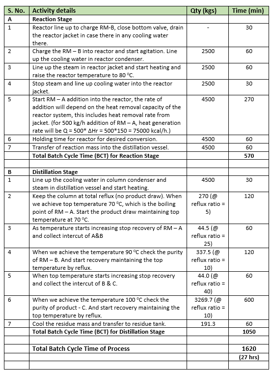
Process Operating Steps
The details of each step are in below table.
Production Capacity
For batch plant design we consider 300 working days or 7200 hrs in a year. Hence, total number of batches for our plant will be = 300*24/BCT = 300*24/27 = 266.7 batches ~ 266 batches/year.
Our per batch production of product – C is 3269.7 kg or 3269.7/1000 = 3.27 MT/batch. Therefore, our plants annual production capacity will be = capacity per batch * batches per year = 3.27*266 = 869.8 MT.
Conclusion
You can use this procedure to carryout the process engineering of your batch plant. For your work you will get a technology package from your R&D department. In this you will get all the information regarding reaction and downstream requirement. After this we do the equipment design for equipment. In our example various equipment are such as reactor, reactor condenser, transfer pump, distillation vessel, distillation column, column condenser, etc.
Next, we design control system requirement for reactor temperature, distillation column temperature, steam flow and reflux flow. Pipe line sizing for process, cooling water, steam and condensate.
Afterwards, P&ID development, equipment layout and elevation drawings are developed. In my future post we will go through all the steps.
Thanks,