In plants liquid-liquid extraction column is used to separate components using solvent. In liquid-liquid extraction process solute is transferred between solvents. Moreover, both the solvents are insoluble in one another. However, the solvent which contain solute we consider it a feed stream. And, other is solvent stream in which solute transfer takes place.
Selection of solvent for extraction is based on many criteria such as boiling point, environment friendly, cost and toxicity.
In extraction process feed and solvent streams mixing enhance the solute transfer from feed to solvent stream. After mixing when this mixture settles, two layers forms. In which upper layer is light phase and bottom layer being heavy phase.
The ratio of solute concentration at equilibrium state between liquid Phase- I and liquid Phase- II is known as distribution coefficient and given by below expression.
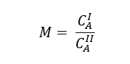
Where, M is distribution coefficient, CAI and CAII are the solute concentration (g/liter) at equilibrium state in Phase- I and Phase- II respectively.
Since, CAI = ρI*yA and CAII = ρII*xA , Therefore, we can write phase equilibrium constant in terms of mass fraction as below
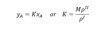
In case of change in densities K may not be constant.
Table of Contents
Batch Extraction System
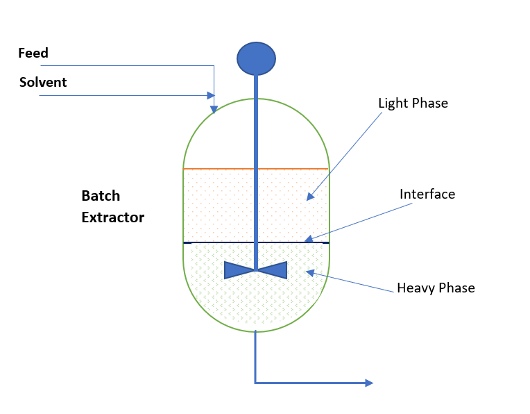
So, conceptually we can visualize an extraction process is the combination of two process operations. First, is mixing and second decantation. In batch extraction systems we use agitated vessel to mix feed and solvent streams. After mixing when equilibrium is achieved between phases mixing is stopped and mass is allowed to settle down. After required settling time, which depends on the density difference and viscosity of continuous phase, two distinct layers form. Further these layers are collected in different vessels. The solute rich layer is our extract phase and the other layer is raffinate phase. This we can see in below sketch:
The settling time for the phases you can estimate by below equation
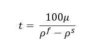
Where, μ is the viscosity (cP) of continuous phase, ρf & ρs are the densities (kg/m3) for feed & solvent respectively.
In case of emulsion formation phase separation becomes difficult. Emulsion is the state in which there is no differentiation between two phases. This problem depends on process temperature and presence of inert solids.
Continuous Liquid – Liquid Extraction System
The hydraulics of extractor column is established by density difference of both phases. Light phase is fed from the bottom side and heavy phase is fed from top side of the extraction column. Inside extraction columns mechanical agitation, trays or packing is used to provide the surface are for solute mass transfer.
Mechanically agitated type extractors are known as Rotating Disc Contact type extractor also. The function of column internals is to form fine droplet of one phase into other phase to enhance solute mass transfer. The phase which is in form of droplets inside extractor is known as disperse phase and other is called continuous phase. If light phase is in disperse form then interface is maintained at top side of the extraction column. Conversely, when light phase is in continuous phase, we maintain interface at the bottom side of the extractor.
Process of Continuous Extraction Column
For efficient operation of the extraction column you should provide precise interface control. Below figure is for the reference to understand an extraction column process. Here, depending of the density of feed or solvent we decide which stream will enter from the top. If solvent is lighter phase this enter into the extraction column from bottom, while feed having higher density enters from the top side of the extraction column. Solvent moves upside and extract the solute from feed stream into it. The extract stream rich in solute overflows from the extractor column and goes for solvent recovery column. Where solvent recovers and recycle back into the extractor column. While, raffinate which is a solute lean phase goes to effluent treatment plant.
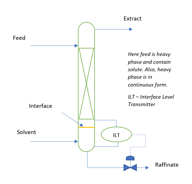
In continuous extraction column there are three control loops. First is feed flow control, second solvent flow control and third is interface level control loop.
How to Get Distribution Coefficient?
In our plant we can conduct shake trial tests to estimate the with Feed and Solvent to derive this data. In this we take known quantity and concentration feed in a flask and add suitable solvent in 1.0: 1.0 volume by volume ratio. After this agitate it for known span of time and settle for a known time. Separate the phases using phase separating flask and get analysis for both the phases. Again, repeat this process with raffinate phase till we achieve the accepted concentration of product in raffinate phase. We can use design the experiments to understand the effect of Feed to Solvent ratio, mixing time and settling time. You can use below format for your shake trial experiments.
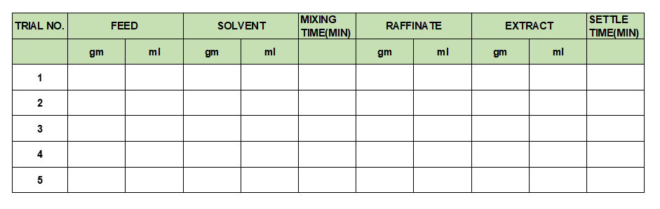
Above trials can give us the practical estimates about number of stages required for extraction column.
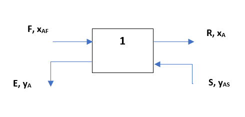
Process Calculations for Single Stage Continuous Extraction System
Let us assume a single stage extraction system as shown below, here raffinate and extract phases are in equilibrium state (i.e., yA = K*xA):
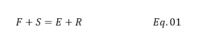
Since phases are in equilibrium and we can take entire stage as a control volume. For steady state total mass balance equation will be as below
Now we can write the mass balance for solute also
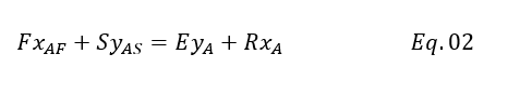
We assume solvent and feed are immiscible, however in reality small miscibility is there. Therefore, we can write below balance for other than solute in both the phases
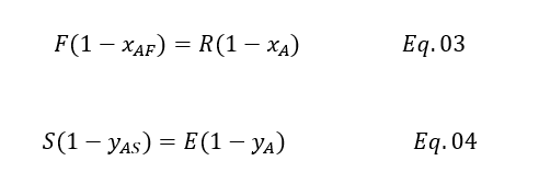
Because other than solute quantity rest is equal at inlet and outlet for both the phases. Suppose you 20% Acetic Acid in feed than rest is water which is 80%. So, water quantity will remain same at inlet and outlet as we have assumed phases are immiscible.
After rearranging Eq. 03 and Eq. 04, we will get below
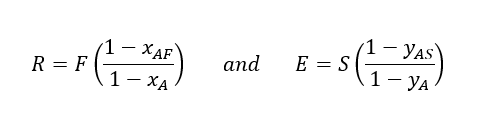
Since, yA = K*xA and substituting the values of R & E in Eq. 01 we will get below
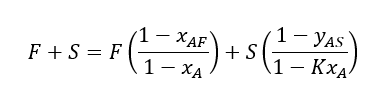
After rearranging and using feed to solvent ratio ψ = F/S, we can get below equation
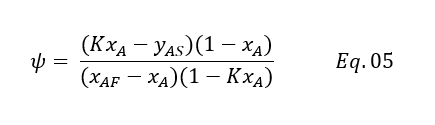
We can write it in quadratic for as below
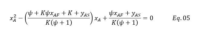
Above equation can be used to estimate the solute concentration going in raffinate phase. Lets us take an example for our calculation.
Example for Single Stage Extraction
1000 kg/h aqueous feed containing 18% wt/wt acetic acid is extracted using 1000 kg/h of ethyl acetate as a solvent. Solvent is pure and the phase equilibrium constant for the system is K = 2.3. For single stage extraction please estimate the acetic acid concentration in the raffinate phase.
Solution:
Here, F = 1000 kg/h, S = 1000 kg/h, xAF = 0.18, yAS = 0, K = 2.30, ψ = F/S = 1.0
Putting above values in Eq. 5 we will get
xA2 – ((1 + 2.30*0.18 + 2.30 + 0)/(2.30*(1 + 1))*xA + (1*0.18 + 0)/(2.30*(1 + 1)) = 0
xA2 – 0.81*xA + 0.04 = 0
Solving above equation, the positive root between 0 and 1 is xA = 0.0528. Therefore, the acetic acid concentration in raffinate will be 5.28% using single stage extraction system. Similarly, we can estimate the value for next stages as well.
Conclusion
You should be clear liquid liquid extraction system design based on theoretical calculation is an approximate result. We should support our calculations with shake trial experiments to get evidence. This will help us to reach over more realistic design. Moreover, we should optimize the feed to solvent ratio (ψ), system temperature, contact time, settling time for efficient extraction design.
Also, in actual situation solvent and feed phases are not completely immiscible and loss of solvent in raffinate is a cost to the business. This solvent loss occurs by two ways, first because of the solubility of solvent in raffinate phase. And, other physical carryover in case of insufficient settling time and poor decantation system design. Therefore, to minimize solvent loss we can use two strategies. This includes the extraction temperature optimization and second providing larger residence time for layer separation.
If you have any questions or comments please mail me. Also, kindly don’t forget to subscribe my site to read future posts.
Thanks,