In chemical industries fluidized bed reactors are used for solid gas reaction. In this we use gases as a fluidizing media to fluidize the solid catalyst, which is a bed of finely divided solid particles. This fine powder is contained in a cylindrical vertical shell, having a grid at the bottom to support the catalyst bed. Fluidizing gases enter from the bottom of the vessel through this catalyst support grid. The flow of fluidizing gases or reactant gases is maintained to ensure sufficient pressure drop across the catalyst support grid. This pressure drop is important to avoid catalyst seepage below the support grid. Minimum recommended pressure drop across grid is around 30% of the total catalyst bed weight. Particle size distribution of the powder solid catalyst can be in the range from 20μ to 250μ.
Because of fluidization solid catalyst bed behaves like a fluid and exhibits fluid like properties such as viscosity. And, behaves like a continuous stirred tank reactor or CSTR, this is the basic major advantage over fixed bed reactor. Gas and solids are in intimate contact and well mixed condition. Thus, even for highly exothermic or endothermic reactions, reactor normally operates at completely isothermal conditions. Moreover, catalyst transportation is possible like a fluid from one vessel to another vessel in case of regeneration requirement.
As catalyst inside the reactor vessel is in fine powder form and its particle size distribution ranges among various sizes. Therefore, during the fluidization process coarser particles fall back inside the bed while finer particles comes out with product gases. So, to avoid catalyst loss we provide cyclones to separate this fine powder from the outgoing gases, which return back into the reactor. These cyclones can be inside the reactor or installed outside also.
Table of Contents
Minimum Fluidization Velocity
When we continuously increase the gas velocity through as packed bed the pressure drop across bed keep on increasing. At a particular gas flow rate, we will reach a stage when pressure drop across the bed becomes equal to the weight of the bed. This situation we know as a starting of fluidization, and corresponding superficial velocity through vessel is the minimum fluidization velocity. A bed of solid particles exhibits the properties of fluids in this state.
When we further increase gas velocity through the bed it behaves in similar way as we see in case of gas induction in a liquid. So, gas flow rates beyond minimum fluidization velocity flow in form of bubbles and pressure drop remains constant across the bed. This is the fluidization state for gas-solid system and we can use the principles of gas-liquid system to understand the reactor behaviour.
To estimate minimum fluidizing velocity, you can use below equation
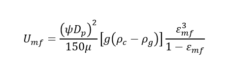
Here, ψ = is the dimensionless parameter sphericity measured value ranges from 0.5 to 1, for a granular solid we can use 0.6 (ψ = As/Ap = (surface area of equivalent sphere/surface area of actual particle))
Ԑmf = is the void fraction at the point of minimum fluidization velocity and also a dimensionless parameter. And a value Ԑmf = 0.5 is typical.
Dp = mean particle diameter we can calculate as
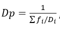
, fi is the fraction of particles with diameter Di
g = gravitational constant, μ = gas viscosity, ρc = catalyst particle density, ρg = gas density
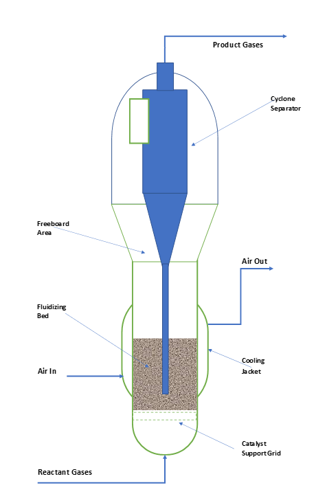
Schematic of Fluidized Bed Reactor
To understand a fluidized bed reactor, you can refer the below figure. In this we can see various major parts comprises Reactor Shell, Catalyst Support Grid, Cyclones, Jacket and Coil for cooling. When reactor is in fluidized state, catalyst level above support grid is known as bed height. The zone above bubbling bed level is called freeboard area. This is the area where heavy catalyst particles separate from outgoing gases by gravity and fall back into the bed. Beyond the freeboard area catalyst particles are pneumatically conveyed and enters into the cyclones. The height above bubbling bed level to reactor outlet is known total disengagement height or TDH.
Fluidized Bed Reactor v/s Fixed Bed Reactor System
Fluidized bed reactors are best suitable for the reactions where we require frequent regeneration of catalyst. Otherwise it is advantageous to go for fixed bed reactor as the conversion will be highest per unit of reactor volume for a given reaction. However, in fixed bed reactors catalyst regeneration is almost impossible because of poor heat transfer. Which leads to localized hot spot generation and runaway conditions in reactor tubes. This results in reactor tube melting and catalyst sintering.
Catalyst Regeneration
In contrast in fluidized bed reactor due to intimate contact of gases with solid and fluidization provides mixed flow conditions. This facilitates almost uniform reactants concentration and temperature throughout the catalyst bed. Which eliminates the possibilities of hot spot formation and provides better temperature control.
Catalyst Handling
Moreover, catalyst replacement in fluidized bed reactor is very easy. Where you can dump the spent catalyst and pneumatically charge the fresh catalyst. While in fixed bed reactor it takes too much time and very tedious job to replace the catalyst. To ensure uniform reactants flow across all the reactor tubes, we need to estimate pressure drop for each and every tube. Also, it very important to ensure proper ratio of inert and catalyst in different segments of the individual tube. Any lapse in this filling process can lead to severe consequences during reactor operation. Therefore, from this point of view fluidized bed reactor is the best option.
Chocking Problems
Furthermore, operation & control of fixed bed reactor is easier than fluidized bed reactor. Because in fluidized bed reactor we need precise control of reactor pressure, flow rates and temperature to ensure efficient fluidization of the catalyst. A pressure disturbance can cause loss of catalyst through cyclones. And this carryover of catalyst with product gases will choke the reactor down stream and you need to shutdown the plant for cleaning of equipment, such as venturi scrubber, condenser, connecting pumps, filters and piping. In case of inlet gases flow interruption catalyst may seep below the catalyst support grid and will chock the bottom of reactor. We don’t see these kinds of problems in fixed bed reactor system, therefore comparatively easy to operate.
Maintenance
From maintenance point of view fixed bed reactors are better option where there are no moving parts inside. Once you fix the reactor it will keep on running without any mechanical failure. While in the case of fluidized bed reactor fine catalyst power is continuously remain in dynamic state. This movement of catalyst causes erosion of reactor internal parts including cyclone inlet, reactor shell and catalyst support grid. Generally, cyclone and support grid nozzles require frequent replacements.
In fluidized bed reactor because of fluidization of catalyst we also face dynamic loading on plant structure. Therefore, to avoid excess vibrations and damage of plant structure we should take care for this dynamic loading during steel structure designing.
Operation & Controls of Fluidized Bed Reactor System
As we discussed above fluidized bed reactor is most suitable where we require continuous regeneration of the catalyst. During reaction step coke forms and deposits on catalyst surface and inside the pores. This coke deposition decreases the activity of the catalyst which reduces the conversion of the reaction. Therefore, to maintain constant conversion and capacity from reactor we need to regenerate the catalyst continuously. We use air for the coke generation, which takes place around 550 – 600 0C.
The major application of fluidized bed reactor you can see in Catalytic Cracker, which the heart of the petroleum refineries. In cracker catalyst particle facilitates the breaking of large molecules in smaller useful molecules of gasoline, diesel, fuel oil, etc. This incoming crude vapour keeps the cracker catalyst in fluidized state. During this reaction coke formation takes place which deposits on the catalyst particle surface and deactivates it. To regenerate it we continuously circulate this catalyst in another vessel to reactivate it using air. This vessel is known as regenerator and coke combustion takes place with air; this air keeps the catalyst bed in fluidized condition. You can refer below figure to understand the catalytic cracking process.
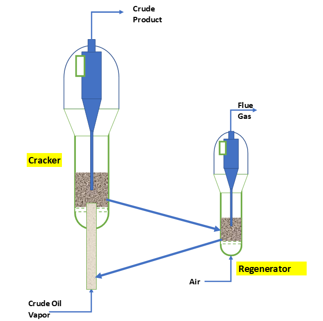
During operation pressure drop across catalyst support grid is important for efficient fluidization. Simultaneously, pressure drop between cracker and regenerator is very critical for smooth circulation of the catalyst.
In fluidized bed reactors cyclone efficiency is very important. Wrong cyclone design will cause of fine particles loss from the catalyst bed. At low fine % gas bubbles will be of bigger sizes and will reduce the contact surface area between solid and gas. Subsequently, this will negatively impact the raw materials conversion. Therefore, to maintain the adequate fines in fluidizing bed is important for smaller size bubbles formation.
Cyclone dip leg design is also very important to minimize the catalyst loss. A wrong diameter of dip leg will allow the channelling of reactants gases from the cyclone dip leg and enhance catalyst loss also.
Conclusion
In this article we discussed about the fluidized bed reactor system. How it works and what are the various advantages and disadvantages in comparison with a fixed bed reactor. Design of fluidized bed is based on minimum fluidization velocity. This we use to estimate the reactor diameter, in actual fluidized bed reactors operates at a higher velocity than minimum fluidization velocity. The actual fluidization velocity can be around 30 to 70 times of minimum fluidization velocity.
Furthermore, we must see for the real-time data analysis of the fluidized bed reactors. This will give us the insight for better operation and improved yield. We can develop Machine learning models to predict the cyclone & catalyst support grid failures.
Thanks for reading and looking forward for your comments and feed backs.